Eureka AIR delivers breakthrough ideas for toughest innovation challenges, trusted by R&D personnel around the world.

Control system and method for power supply switching of operation machine and operation machine

A technology for power switching and operating machinery, which is applied in the direction of emergency power arrangement, electrical components, circuit devices, etc., and can solve problems such as the need to connect the power supply and the normal shutdown of the engine

Active Publication Date: 2022-02-08
SANY AUTOMOBILE HOISTING MACHINERY
View PDF7 Cites 0 Cited by
  • Summary
  • Abstract
  • Description
  • Claims
  • Application Information

AI Technical Summary

Problems solved by technology

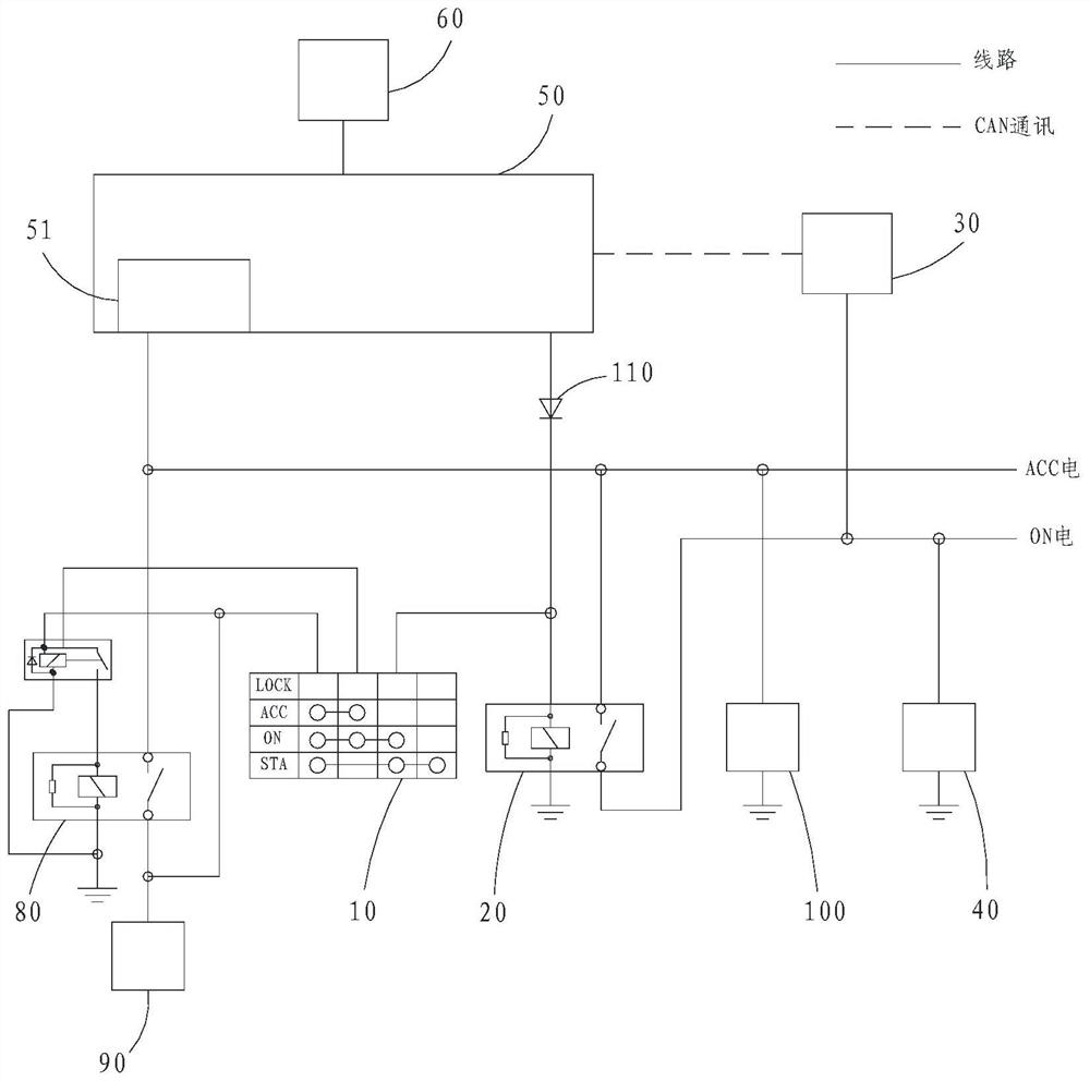
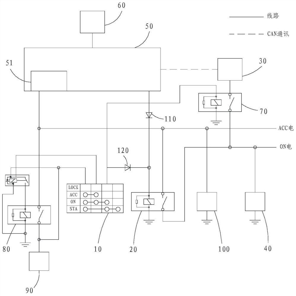
[0004] The present invention provides a control system for switching power sources of working machinery, which is used to solve the power supply requirements for vehicle-mounted air conditioners, vehicle lighting and various relays during the switching process of two power sources for engine operation and plug-in operation in the prior art. For the connection problem, by adjusting the ON gear relay, ensure that the engine can be turned off normally after the key is pulled out, and at the same time, the ON gear relay is in the pull-in state, and the ON gear power supply can still provide power to the electrical equipment.
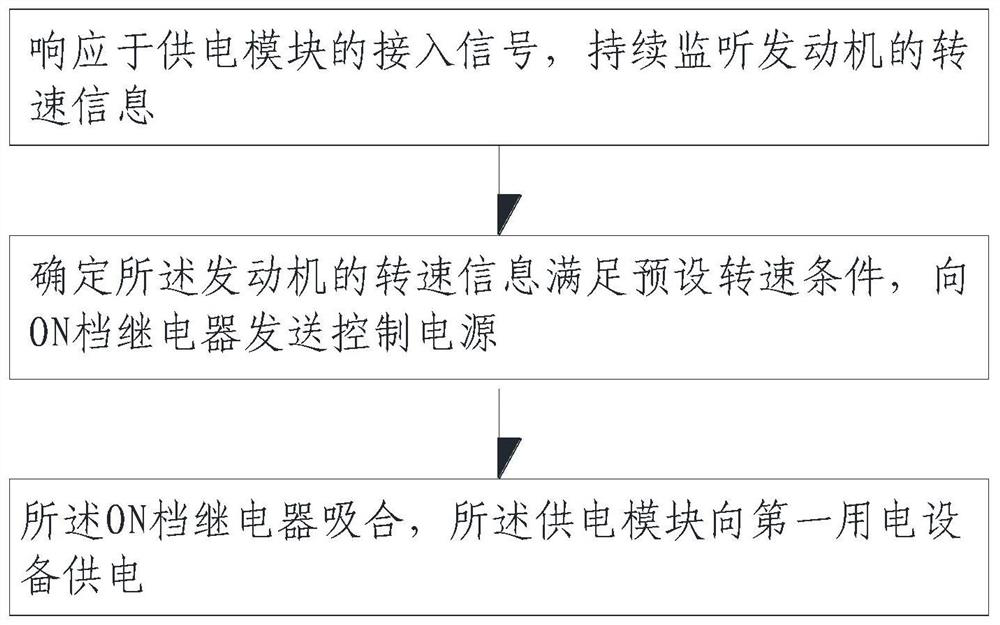
[0005] The present invention also provides a control method for switching power sources of working machinery, which is used to solve the problem of power supply required for the work of vehicle air conditioners, vehicle lighting and various relays during the switching process of the two power sources of engine operation and plug-in operation in the prior art. The problem that needs to be connected, by monitoring the speed information of the engine, when the engine is detected to be off, the external power supply is used to supply power to the electrical equipment

Method used


Image

  • Control system and method for power supply switching of operation machine and operation machine
  • Control system and method for power supply switching of operation machine and operation machine
  • Control system and method for power supply switching of operation machine and operation machine

Examples


Embodiment Construction

[0069] In order to make the purpose, technical solutions and advantages of the embodiments of the present invention clearer, the technical solutions in the embodiments of the present invention will be clearly and completely described below in conjunction with the drawings in the embodiments of the present invention. Obviously, the described embodiments It is a part of embodiments of the present invention, but not all embodiments. Based on the embodiments of the present invention, all other embodiments obtained by persons of ordinary skill in the art without making creative efforts belong to the protection scope of the present invention.

[0070] In the description of the embodiments of the present invention, it should be noted that the terms "center", "longitudinal", "transverse", "upper", "lower", "front", "rear", "left", "right" , "vertical", "horizontal", "top", "bottom", "inner", "outer" and other indicated orientations or positional relationships are based on the orientat...


PUM


Abstract

The invention provides a control system and method for power switching of an operation machine and the operation machine. The system comprises an ignition lock, an ON-gear relay, an engine, first electric equipment, a controller and a power supply module. The ignition lock is connected with the ON gear relay; the controller is in communication connection with the engine; the controller is electrically connected with the ON-gear relay and the power supply module. When the controller monitors that the engine flames out, the controller sends a control power source to the ON-gear relay to achieve actuation of the ON-gear relay, and the power supply module supplies power to the first electric equipment. By regulating and controlling the ON-gear relay, it is guaranteed that after a get-off key is pulled out, an engine can normally flame out, meanwhile, the ON-gear relay is in a pull-in state, an ON-gear power source is switched on, and power can still be supplied to electric equipment.

Description

technical field [0001] The invention relates to the technical field of engineering machinery, in particular to a control system and method for switching power sources of working machinery and working machinery. Background technique [0002] At present, with the vigorous development of the construction machinery industry, in order to achieve "carbon neutrality" and "carbon peak" to fully promote the new energy industry, construction machinery using new energy as power has increasingly become the future development trend of the industry. [0003] Cranes are engineering equipment in the field of construction machinery. There is a kind of plug-in crane, which uses electric energy to operate under the condition of electricity, and uses the most economical engine to operate under the condition of no electricity. In the process of switching between the two power sources of engine operation and plug-in operation, the ACC gear and ON gear power required for the work of the vehicle ai...

Claims


Application Information

Patent Timeline
Patent Type & Authority Applications(China)
IPC IPC(8): H02J9/06B60R16/033
CPCH02J9/061H02J9/068B60R16/033
Inventor 杜鑫李韬李永圣
Owner SANY AUTOMOBILE HOISTING MACHINERY
Why Eureka
Eureka Blog
Learn More