Resin lens injection mold

A technique for resin lenses and injection molds, which can be applied to household appliances, other household appliances, optical components, etc., and can solve problems such as insufficient demoulding effect, affecting product quality, and poor heat dissipation of resin lenses.

Pending Publication Date: 2022-02-15
YEJIA OPTICAL TECH GUANGDONG CORP
View PDF4 Cites 3 Cited by
  • Summary
  • Abstract
  • Description
  • Claims
  • Application Information

AI Technical Summary

Problems solved by technology

[0004] Based on this, it is necessary to address the problems of the prior art and provide a resin lens injection mold, which passes through the first cooling mechanism in the first cooling cavity of the upper mold base and the second cooling mechanism in the second cooling cavity of the lower mold base. At the same time, the mechanism cools the unseparated movable mold and fixed mold for one end of time in advance, so that the resin lens in the mold cavity is uniformly cooled. After cooling for one end of time, the upper mold frame and the movable mold rise, and then pass through the The second cooling mechanism cools the bottom of the resin lens in the second injection cavity, so as to better cool the resin lens and demould, which solves the problem of poor local heat dissipation during injection molding of the resin lens, which will eventually lead to insufficient demoulding effect , technical issues affecting product quality

Method used


Image

  • Resin lens injection mold
  • Resin lens injection mold
  • Resin lens injection mold

Examples


Embodiment Construction

[0050] In order to further understand the features, technical means, and specific objectives and functions achieved by the present invention, the present invention will be further described in detail below in conjunction with the accompanying drawings and specific embodiments.

[0051] Such as Figure 1 to Figure 7 As shown, this application provides:

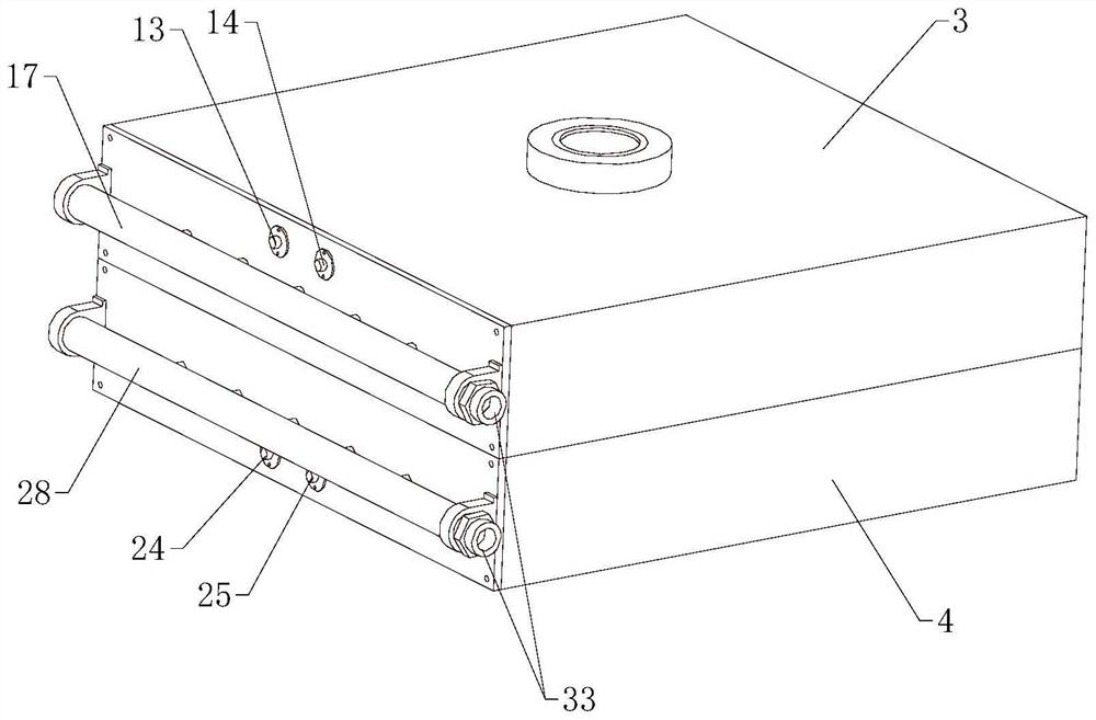
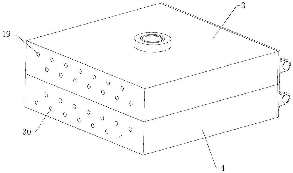
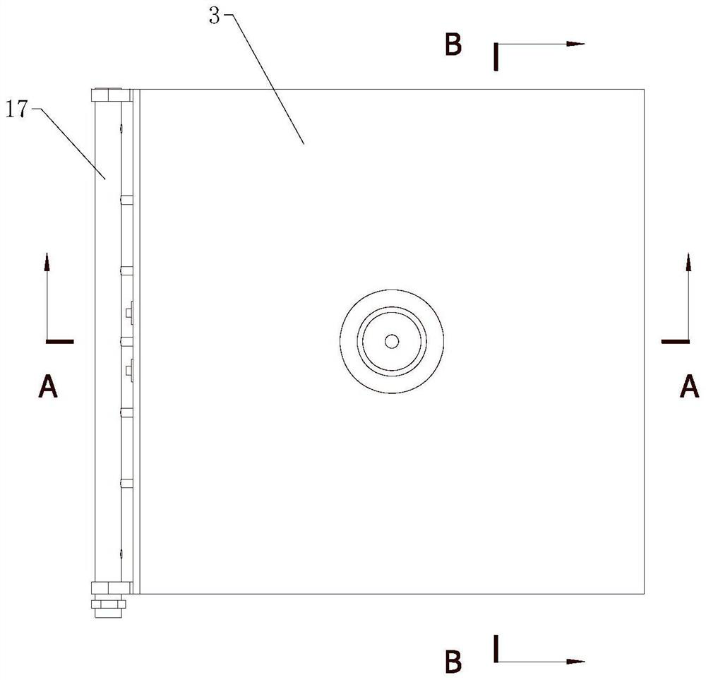
[0052] A resin lens injection mold, comprising a fixed mold 1 and a movable mold 2, the fixed mold 1 is fixedly mounted on an upper mold frame 3, the fixed mold 1 has a convex part for forming a resin lens, and the movable mold 2 is fixedly mounted on a lower mold frame 4 Above, the movable mold 2 has a concave part for resin lens molding. The concave part corresponds to the convex part up and down. When the mold is closed, there is a gap equal to the thickness of the resin lens between the concave part and the convex part. The gap between the concave part and the convex part forms In order to form a mold cavity matching the s...


PUM


Abstract

The invention relates to the technical field of injection molds, and in particular, relates to a resin lens injection mold which comprises a fixed mold body and a movable mold body; the fixed mold body is fixedly mounted on an upper mold frame and provided with a convex part used for resin lens forming, and the movable mold body is fixedly mounted on a lower mold frame and provided with a concave part used for resin lens forming; a gap between the concave part and the convex part forms a mold cavity matched with the shape of the resin lens, and the mold cavity comprises a plurality of first injection molding cavities and a plurality of second injection molding cavities; and the plurality of first injection molding cavities are provided, the number of the second injection molding cavities is the same as that of the first injection molding cavities, the second injection molding cavities are matched with the shape of the resin lens, the upper mold frame is provided with a first cooling cavity, a first cooling mechanism is arranged in the first cooling cavity, the lower mold frame is provided with a second cooling cavity, and a second cooling mechanism is arranged in the second cooling cavity. Through mutual cooperation of the first cooling mechanism and the second cooling mechanism, bidirectional cooling is achieved in advance, and the injection molding cooling demolding efficiency is improved.

Description

technical field [0001] The invention relates to the technical field of injection molds, in particular to a resin lens injection mold. Background technique [0002] Injection mold is a tool for producing plastic products; it is also a tool for giving plastic products complete structure and precise dimensions. Injection molding, also known as injection molding, is a molding method of injection and molding. The advantages of the injection molding method are fast production speed, high efficiency, automatic operation, various designs and colors, simple to complex shapes, large to small sizes, accurate product sizes, easy replacement of products, and complex shapes. Parts, injection molding is suitable for mass production and complex shape products and other molding processing fields. [0003] When the injection mold is being injected, it needs to be cooled and demolded in the later stage. However, during the cooling and demoulding process of special-shaped products, the coolin...

Claims


Application Information

Patent Timeline
Patent Type & Authority Applications(China)
IPC IPC(8): B29C45/73B29C33/04B29L11/00
CPCB29C45/73B29C45/7312B29C45/7337B29C33/04B29C33/046B29L2011/0016
Inventor 南基学
Owner YEJIA OPTICAL TECH GUANGDONG CORP
Why Eureka
Try Eureka