Upper material ejecting device of hot die forging press machine

A technology of hot die forging presses and ejector devices, applied in forging/pressing/hammer devices, forging/pressing/hammering machinery, heating/cooling equipment, etc. Thickness positioning, product offset and other issues to achieve the effect of increasing stability and service life, improving service life and increasing mechanical strength

Active Publication Date: 2021-11-23
江苏兴锻智能装备科技有限公司
View PDF5 Cites 0 Cited by
  • Summary
  • Abstract
  • Description
  • Claims
  • Application Information

AI Technical Summary

Problems solved by technology

The upper ejector device of the hot die forging press of the utility model keeps the forging on the lower die and will not be taken out with the upper die, which ensures the stability of the position of the forging and can ensure that the forging can stay after each forging of the press In the lower mold cavity, the failure rate of the automatic line is reduced and the start-up rate of the automatic line is increased. Although this application can cool the upper ejector device, when the debris brought by the upper ejector column cannot be removed, when too much debris enters the After the jacking device is installed, it will directly affect the stability and life of the jacking column, and when the formwork is in contact with the product, it cannot be positioned according to the thickness of the product, and it is easy to cause the product to shift during operation. Therefore, we propose A loading and ejecting device for a hot die forging press, so as to solve the above-mentioned problems

Method used


Image

  • Upper material ejecting device of hot die forging press machine
  • Upper material ejecting device of hot die forging press machine
  • Upper material ejecting device of hot die forging press machine

Examples


Embodiment Construction

[0057] The following description serves to disclose the present invention to enable those skilled in the art to carry out the present invention. The preferred embodiments described below are only examples, and those skilled in the art can devise other obvious variations.

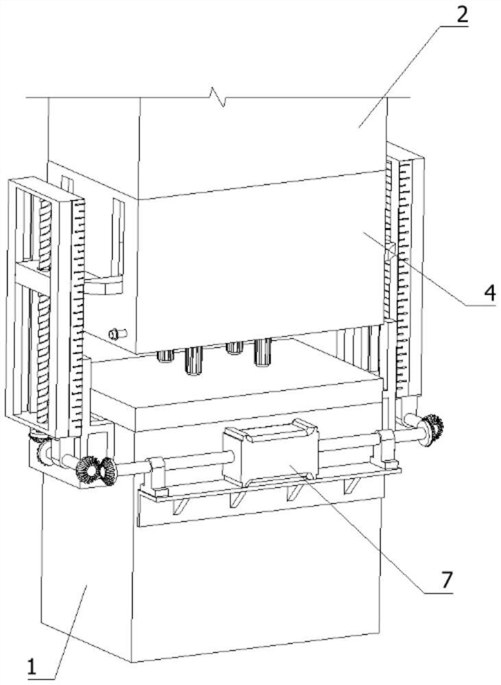
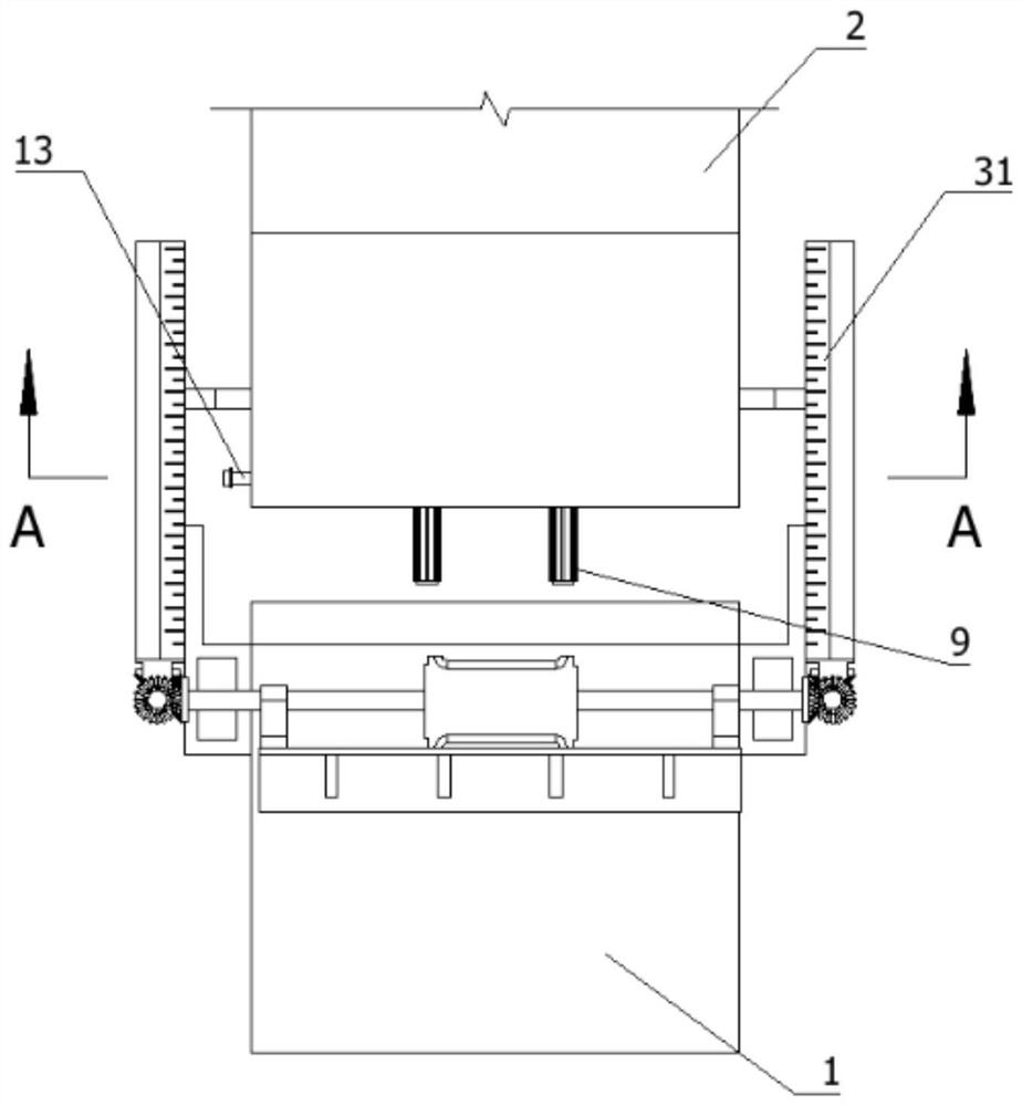
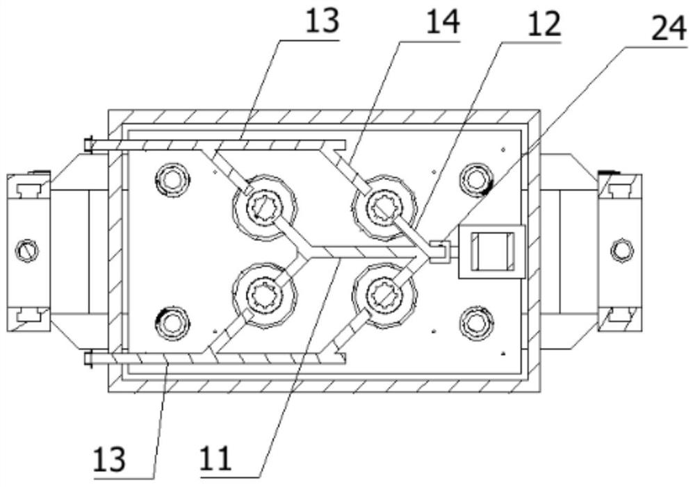
[0058] In order to solve the technical problem of how to position the product and prevent the product from bonding with the formwork 3 and how to improve the service life of the ejector column, such as Figure 1 to Figure 5 As shown, the following technical solutions are provided:

[0059] A loading and ejecting device for a hot die forging press, comprising a frame 1, a slider 2 positioned directly above the frame 1, a mold frame 3 arranged at the bottom of the slider 2, and further comprising:

[0060] The upper ejection mechanism 4 is arranged between the slider 2 and the mold frame 3;

[0061] The cooling anti-blocking mechanism 5 is arranged inside the upper ejection mechanism 4;

[0062] The ejectio...


PUM


Abstract

The invention relates to the technical field of hot die forging press machines, in particular to an upper material ejecting device of a hot die forging press machine. The device comprises a rack, a sliding block positioned over the rack, a die frame arranged at the bottom of the sliding block and an upper ejection mechanism. A cooling anti-blocking mechanism is further included. A pair of ejection adjusting mechanisms is provided. A synchronous driving mechanism is included. The ejection mechanism comprises a rectangular hollowed box, a lifting flat plate and a plurality of upper ejecting columns. The cooling anti-blocking mechanism comprises anti-blocking cooling sleeves which are in one-to-one correspondence with the upper ejecting columns and a main blowing pipe, and discharging pipes extending towards the exterior of the rectangular hollowed box are arranged on the two sides of the interior of the rectangular hollowed box. Each ejection adjusting mechanism comprises a lifting block. According to the device, the bottom of each upper ejecting column can abut against the top of a product in advance according to the thickness of the product, the product can be positioned, meanwhile, the product can be prevented from being bonded to the bottom of the die frame in the demolding process, and chippings brought in by the upper ejecting columns can be collected and discharged. And the stability of the upper ejecting columns is improved and the service life of the upper ejecting columns is prolonged.

Description

technical field [0001] The invention relates to the technical field of hot forging presses, in particular to a loading and ejecting device for hot forging presses. Background technique [0002] The hot die forging press is a series of products produced by introducing the world's advanced technology. The hot die forging press is used in the manufacturing of automobiles, tractors, internal combustion engines, ships, aviation, mining machinery, petroleum machinery, hardware tools, etc., for die forging and finishing forgings of ferrous and non-ferrous metals The forgings produced have the advantages of high precision, high material utilization rate, high productivity, easy automation, low requirements for workers' operation skills, low noise and vibration, etc. Therefore, they are widely used in modern forging production and are indispensable for modern forging production. Lack of high precision forging equipment. [0003] The patent application number CN201822258133.5 disclo...

Claims


Application Information

Patent Timeline
Patent Type & Authority Applications(China)
IPC IPC(8): B21J13/14B21J13/00B21J5/02B21K29/00B08B5/02
CPCB21J13/14B21J13/00B21J5/02B21K29/00B08B5/02Y02P70/10
Inventor 李江国赵兰磊于勇涛狄智程
Owner 江苏兴锻智能装备科技有限公司
Why Eureka
Try Eureka