
Flow rate limiting method, related network equipment and storage medium

A technology of network equipment and traffic, applied in the field of communication, can solve problems such as unfavorable network resources of operators, reduced user experience, and normal transmission of packets

Pending Publication Date: 2022-02-18
HUAWEI TECH CO LTD
View PDF0 Cites 1 Cited by
  • Summary
  • Abstract
  • Description
  • Claims
  • Application Information

AI Technical Summary

Problems solved by technology

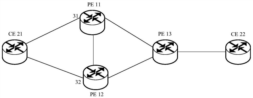
Considering that PE1 and PE2 can perform load sharing, if the rate limit of both PE1 and PE2 is set to 50 Mbps, it is difficult to ensure absolute load balancing on both sides during the actual operation of the network. User traffic is forwarded through the PE1 side, that is, the actual user traffic rate is limited to 50Mbps, which affects the normal transmission of packets and reduces user experience
However, if the speed limit values ​​of PE1 and PE2 are both set to 100 Mbps in order to ensure that the user experience is not lower than expected, the actual peak speed limit of user traffic is 200 Mbps, which is not conducive to the reasonable allocation of the limited network by the operator. resource

Method used


Image

  • Flow rate limiting method, related network equipment and storage medium
  • Flow rate limiting method, related network equipment and storage medium
  • Flow rate limiting method, related network equipment and storage medium

Examples


Embodiment Construction

[0079] In order to make the purpose, technical solution and advantages of the present application clearer, the implementation manner of the present application will be further described in detail below in conjunction with the accompanying drawings.

[0080] It should be understood that the "plurality" mentioned in this application means two or more. In the description of this application, unless otherwise specified, " / " means or means, for example, A / B can mean A or B; "and / or" in this article is just a description of the relationship between associated objects, Indicates that there may be three relationships, for example, A and / or B, may indicate: A exists alone, A and B exist simultaneously, and B exists alone. In addition, in order to clearly describe the technical solution of the present application, words such as "first" and "second" are used to distinguish the same or similar items with basically the same function and effect. Those skilled in the art can understand that...


PUM


Abstract

The invention discloses a flow rate limiting method, related network equipment and a system, and belongs to the technical field of communication. In the method, third network equipment is connected to first network equipment and second network equipment in a multi-homing manner. The first network equipment can determine the interface limited bandwidth of the first network equipment according to the interface spare bandwidth of the second network equipment and the configuration bandwidth of a second interface. Subsequent first network equipment can limit user traffic according to the interface limited bandwidth. The first network equipment and the second network equipment are used for carrying out load sharing on the user traffic, so that the interface limited bandwidth determined by the first network equipment according to the interface spare bandwidth of the second network equipment, namely according to the bandwidth occupation condition of the second network equipment, is relatively accurate, and the first network equipment can limit the speed of the user traffic more reasonably according to the interface limiting bandwidth, so that the purpose of saving network resources on the basis of not damaging the user experience is achieved.

Description

technical field [0001] The present application relates to the technical field of communications, and in particular to a flow rate limiting method, related network equipment and storage media. Background technique [0002] A virtual private network (Virtual Private Network, VPN) technology is widely used in the network design of major operators. The VPN includes multiple provider edge (Provider Edge, PE) devices, and the multiple PE devices are connected to each other. A customer edge (Customer Edge, CE) device can be connected to a PE device in the VPN, so that the user equipment mounted on the CE device can access the VPN. [0003] Currently, to improve reliability, a dual-homing and active-active solution can be used. Specifically, the CE device is dual-homed to the PE1 device and the PE2 device. PE1 and PE2 forward user uplink traffic from CE devices to other devices in a load-sharing manner, and forward user downlink traffic from other devices to CE devices in a load-...

Claims


Application Information

Patent Timeline
Patent Type & Authority Applications(China)
IPC IPC(8): H04L47/10H04L47/125H04L41/0896H04L12/46
CPCH04L47/10H04L47/125H04L41/0896H04L12/4641H04L47/22H04L45/04H04L47/822H04L47/263H04L47/31
Inventor 刘军
Owner HUAWEI TECH CO LTD
Learn More