Antenna switching method and system and mobile terminal equipment

An antenna switching, mobile terminal technology, applied in diversity/multi-antenna systems, radio transmission systems, transmission systems, etc.

Pending Publication Date: 2022-02-22
KUNSHAN RUIXIANG XUNTONG COMM TECHCO
View PDF0 Cites 0 Cited by
  • Summary
  • Abstract
  • Description
  • Claims
  • Application Information

AI Technical Summary

Problems solved by technology

[0003] The purpose of the present invention is to provide an antenna switching method and system, and mobile terminal equipment to s

Method used


Image

  • Antenna switching method and system and mobile terminal equipment
  • Antenna switching method and system and mobile terminal equipment
  • Antenna switching method and system and mobile terminal equipment

Examples


Embodiment Construction

[0030] The antenna switching method, system, and mobile terminal equipment proposed by the present invention will be further described in detail below in conjunction with the accompanying drawings and specific embodiments. It should be noted that all the drawings are in a very simplified form and use imprecise scales, and are only used to facilitate and clearly assist the purpose of illustrating the embodiments of the present invention. In addition, the structures shown in the drawings are often a part of the actual structure. In particular, each drawing needs to display different emphases, and sometimes uses different scales.

[0031] It should be noted that "first", "second", etc. in the specification, claims and description of the drawings of the present invention are used to distinguish similar objects in order to describe the embodiments of the present invention, and are not used to describe specific It is to be understood that the constructions so used are interchangeab...


PUM


Abstract

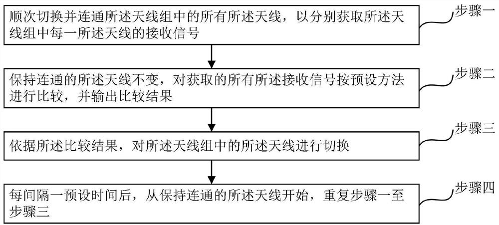
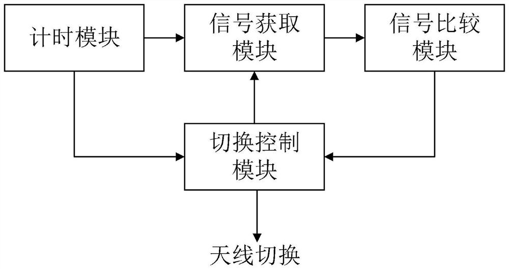
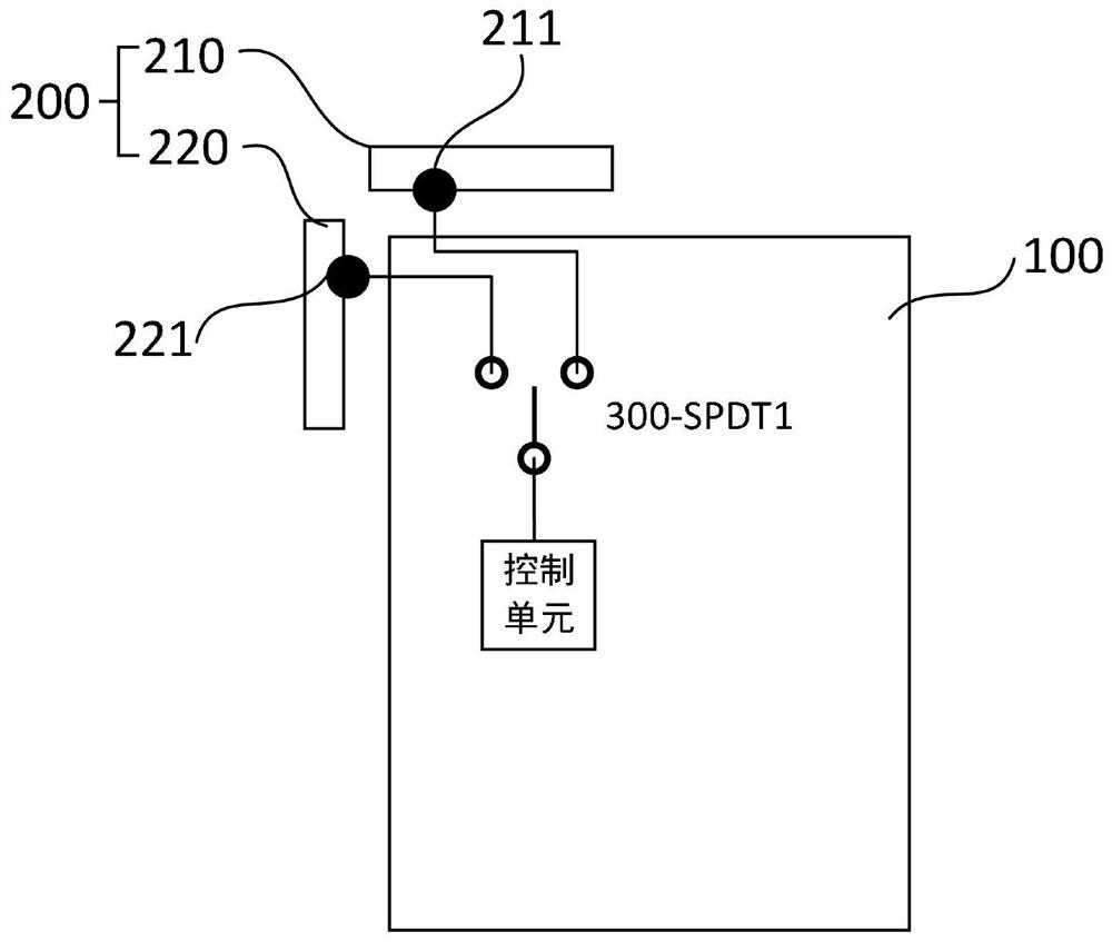
The invention provides an antenna switching method and system, and mobile terminal equipment. The method comprises the steps of sequentially switching and communicating all antennas in an antenna group, so as to obtain a receiving signal of each antenna in the antenna group, keeping the connected antennas unchanged, comparing all the obtained receiving signals according to a preset method, and outputting a comparison result, switching the antennas in the antenna group according to the comparison result, and repeating the steps from the antenna which is kept communicated every preset time. The receiving signals of antennas are obtained when each antenna in an antenna group is connected, all the receiving signals are compared, and the switching of the antennas in the antenna group is controlled according to a comparison result; in addition, after a preset time, the process is repeated, so that continuous switching of the antenna can be realized. Due to the fact that the directions of the antennas in the antenna group are different, the antenna group can receive signals in different directions under the condition that the number of the antennas is not increased through switching of the antennas.

Description

technical field [0001] The present invention relates to the technical field of wireless communication, in particular to an antenna switching method and system, and a mobile terminal device. Background technique [0002] At present, when designing antennas for mobile terminals such as mobile phones, a single feeding method is usually adopted, the matching circuit cannot be adjusted flexibly, and the resonant frequency of the antenna is basically fixed. performance of the antenna. In recent years, with the popularization of 5G technology, the frequency of 5G communication is getting higher and higher, and the requirements for the directionality of communication antennas of 5G equipment are also getting higher and higher. At present, antennas with a single feeding mode in mobile terminals such as mobile phones cannot meet the requirements. In order to solve this problem, in the prior art, the number of antennas is usually increased to solve the problem that the antennas recei...

Claims


Application Information

Patent Timeline
IPC IPC(8): H04B7/06H04B7/08
CPCH04B7/0602H04B7/0805
Inventor 张旭东
Owner KUNSHAN RUIXIANG XUNTONG COMM TECHCO
Why Eureka
Try Eureka