Medical limb auxiliary rehabilitation treatment chair

A technology for rehabilitation treatment and medical treatment, applied in physical therapy, medical transportation, massage auxiliary supplies, etc., which can solve the problems of inconvenient hand or leg exercise for patients, inconvenient movement for patients, and single function

Pending Publication Date: 2022-03-01
赵博熹
View PDF20 Cites 0 Cited by
  • Summary
  • Abstract
  • Description
  • Claims
  • Application Information

AI Technical Summary

Problems solved by technology

[0005] In order to overcome the shortcomings of the existing wheelchairs, which have relatively single functions and are inconvenient for patients to move by themselves, and it is not convenient to exercise the hands or legs of patients, the technical problem to be solved by the present invention is to provide a wheelchair that is convenient for patients to move by themselves. , and is conducive to the patient's hands or legs to exercise the corresponding medical limb-assisted rehabilitation chair

Method used


Image

  • Medical limb auxiliary rehabilitation treatment chair
  • Medical limb auxiliary rehabilitation treatment chair
  • Medical limb auxiliary rehabilitation treatment chair

Examples


Embodiment 1

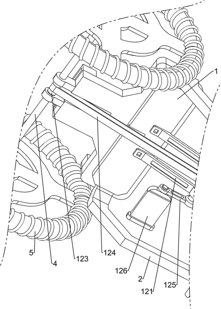
[0039] A medical limb-assisted rehabilitation chair, such as Figure 1-10As shown, it includes a first connecting plate 1, a first connecting rod 2, a runner 3, a first rotating shaft 4, a tire 5, a handrail 6, a backing plate 7, a backrest mechanism 8, a massage mechanism 9 and an extruding mechanism 10. Two first connecting rods 2 are welded symmetrically on the left and right sides of the bottom of a connecting plate 1, and the front sides of the two first connecting rods 2 are all rotatably equipped with runners 3, and the rear side of the first connecting plate 1 is rotatably connected. There is a first rotating shaft 4, and the left and right sides of the first rotating shaft 4 are symmetrically provided with two tires 5 through a key connection mode, and the outer sides of the two tires 5 are connected with handrails 6 through a bolt connection mode, and the first connecting plate 1 The top is equipped with a backing plate 7 in the form of screw connection, and the back...

Embodiment 2

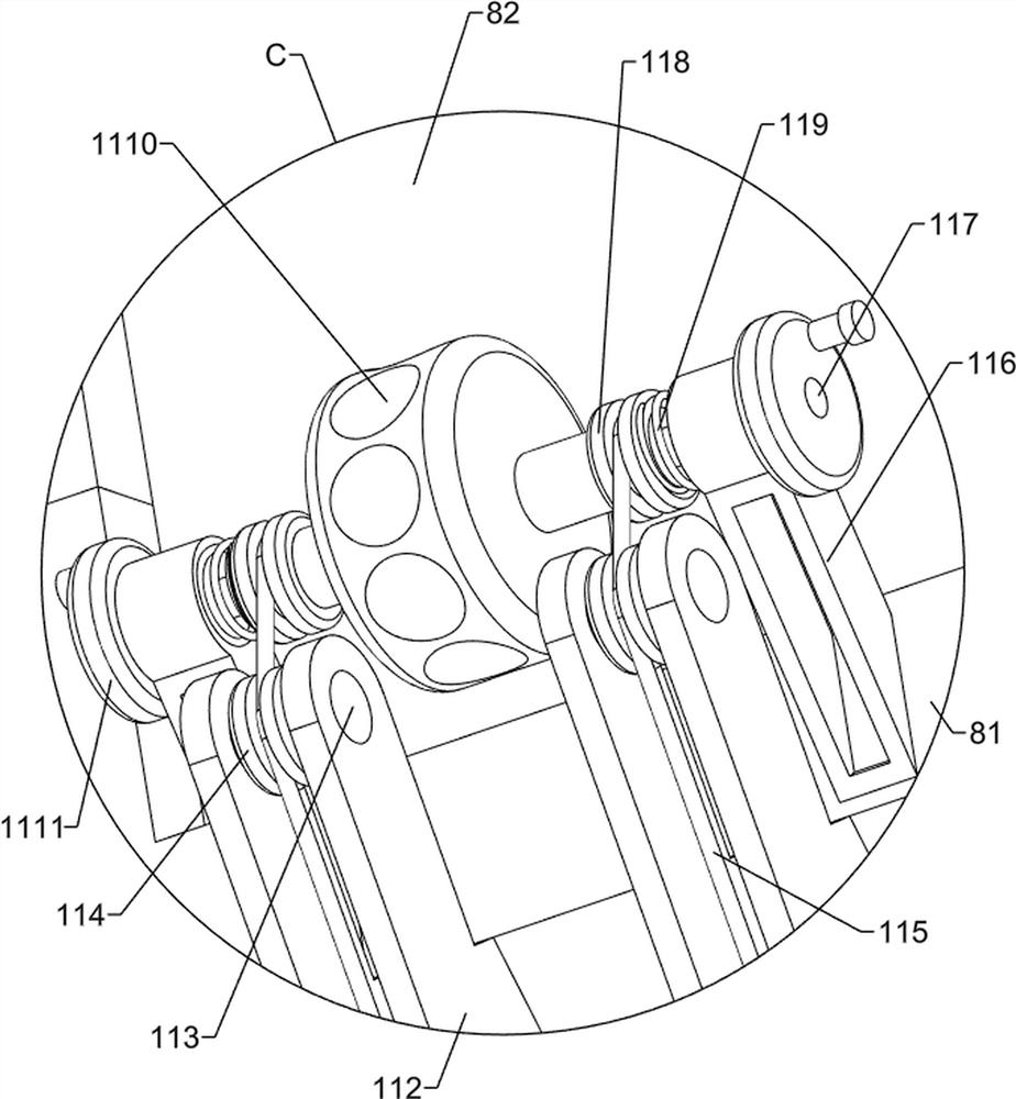
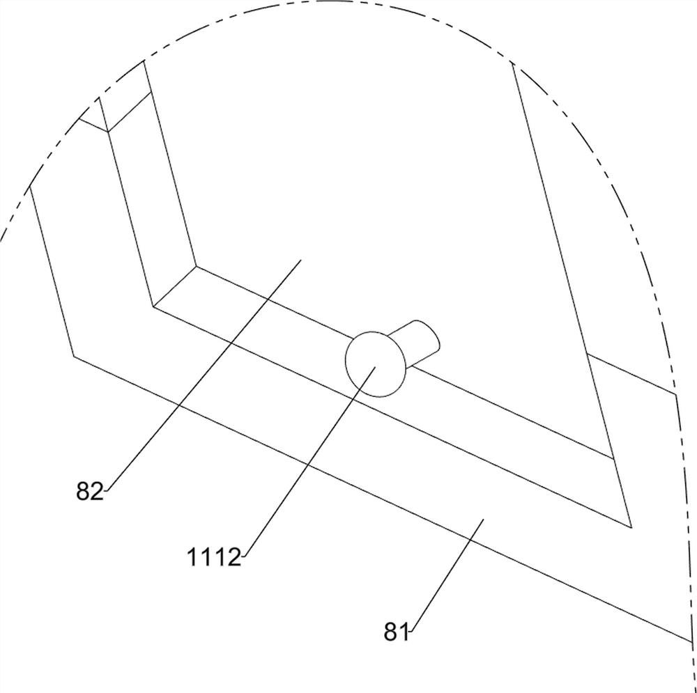
[0045] On the basis of Example 1, such as figure 2 , Figure 11 , Figure 12 , Figure 13 and Figure 14 As shown, a vibration mechanism 11 is also included, and the vibration mechanism 11 includes a winding wheel 111, a first support plate 112, a second rotating shaft 113, a smooth wheel 114, a stay cord 115, a support block 116, a second connecting shaft 117, a fixed Pulley 118, scroll spring 119, recessed disk 1110, rotating disk 1111 and fixed ball 1112, the left and right sides of the middle part of the first rotating shaft 4 are all provided with winding wheel 111 by one-way gear, lean on the left and right sides of plate 81 rear side bottom Two support blocks 116 and four first support plates 112 are symmetrically welded, and the four first support plates 112 are all located below the two support blocks 116, and the top of the two support blocks 116 is rotatably provided with a second The connection shaft 117, the left and right sides of the second connection shaft...

Embodiment 3

[0049] On the basis of Example 2, such as figure 1 , figure 2 and Figure 17 As shown, a stretching mechanism 13 is also included, and the stretching mechanism 13 includes a second fixed plate 131, a pressing plate 132, a third handle 133 and a fourth spring 134, and the bottoms of the two first connecting rods 2 are symmetrically welded with two A second fixing plate 131, a pressing plate 132 is slidably connected between the middle parts of the two second fixing plates 131, and a third handle 133 is connected to the middle position of the top of the pressing plate 132 by screw connection, and the two second fixing plates 131 A fourth spring 134 is connected between the upper part of the upper part and the top of the pressing plate 132 .

[0050] When the patient is alternately stepping on the pedals 126 to exercise the legs, he can sit on the backing plate 7, pull the third handle 133 upwards, and lift the pressing plate 132 to slide upwards. At this moment, the fourth sp...


PUM


Abstract

The invention relates to a rehabilitation treatment chair, in particular to a limb auxiliary rehabilitation treatment chair for medical treatment. The invention provides the medical limb auxiliary rehabilitation treatment chair which is convenient for the patient to move by himself/herself and is favorable for the hand or leg of the patient to do corresponding exercise. A medical limb auxiliary rehabilitation treatment chair comprises a first connecting plate, first connecting rods, rotating wheels, a first rotating shaft and the like, the two first connecting rods are symmetrically installed on the left side and the right side of the bottom of the first connecting plate, the rotating wheels are rotationally arranged on the front sides of the two first connecting rods, and the first rotating shaft is rotationally connected to the rear side of the first connecting plate. By pushing the armrests to rotate, the rehabilitation treatment chair can be moved; a third connecting plate can be lifted upwards with a hand, a second connecting rod can drive a protection plate and a sponge roller to slide under the guiding effect of a guide plate, the sponge roller can conduct rolling massage on the arms of the patient, the arms of the patient can be exercised easily, and therefore the arms of the patient can be effectively recovered easily.

Description

technical field [0001] The invention relates to a rehabilitation treatment chair, in particular to a limb-assisted rehabilitation treatment chair for medical use. Background technique [0002] When the patient's limbs such as hands or legs are injured, it takes a period of cultivation to gradually recover. When the patient is in the process of rehabilitation, due to inconvenient movement but wants to exercise by walking, usually with the help of a wheelchair or crutches Use assistive devices to move. However, the current wheelchair has certain limitations due to its relatively single function, and it needs the assistance of others to move the wheelchair. Rehabilitation of the head or legs is less efficient. [0003] Therefore, it is necessary to develop a medical limb-assisted rehabilitation chair that is convenient for the patient to move by himself and helps the patient's hands or legs to exercise accordingly. Contents of the invention [0004] (1) Technical problems ...

Claims


Application Information

Patent Timeline
Patent Type & Authority Applications(China)
IPC IPC(8): A61G5/00A61G5/10A61G5/12A61H15/00A63B23/04
CPCA61G5/00A61G5/10A61G5/125A61H15/0078A63B23/04A61H2015/0014A61H2205/081
Inventor 黄满招
Owner 赵博熹
Why Eureka
Try Eureka