Unlock instant, AI-driven research and patent intelligence for your innovation.
Inductor component
What is Al technical title?
Al technical title is built by PatSnap Al team. It summarizes the technical point description of the patent document.
A technology of inductors and components, applied in the field of inductor components, can solve the problems of increasing the wiring length, and achieve the effect of ensuring the wiring length
Pending Publication Date: 2022-03-01
MURATA MFG CO LTD
View PDF1 Cites 0 Cited by
Summary
Abstract
Description
Claims
Application Information
AI Technical Summary
This helps you quickly interpret patents by identifying the three key elements:
Problems solved by technology
Method used
Benefits of technology
Problems solved by technology
However, in the inductor component described in Patent Document 1, linear or curved inductor wiring is arranged, and there is a limit to increasing the wiring length while suppressing an increase in DC resistance.
Method used
Image
Click on the blue label to locate the original text in one second.
Reading with bidirectional positioning of images and text.
Examples
no. 1 approach >
[0040] Hereinafter, a first embodiment of the inductor component will be described. In addition, in the drawings, constituent elements may be enlarged and shown in order to facilitate understanding. The dimensional ratios of components may differ from actual dimensional ratios or from dimensional ratios in other drawings.
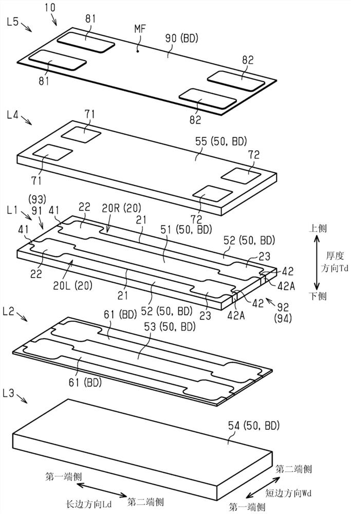
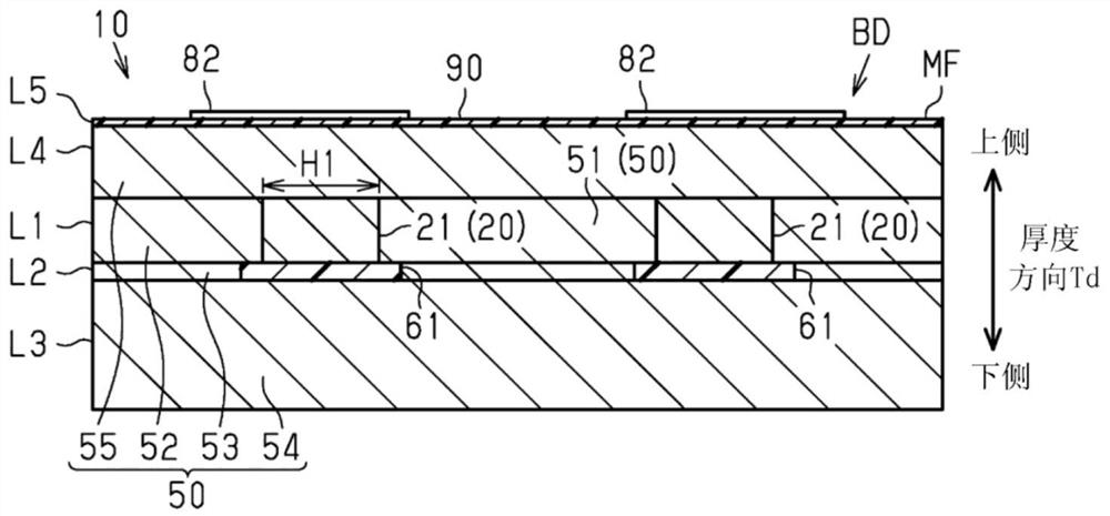
[0041] Such as figure 1 As shown, the inductor component 10 as a whole has a structure in which five layers are stacked in the thickness direction Td. In addition, in the following description, one side in the thickness direction Td is set as an upper side, and the opposite side is set as a lower side.
[0042] The first layer L1 includes two inductor wirings 20 , first support wiring 41 and second support wiring 42 extending from each inductor wiring 20 , an inner magnetic circuit portion 51 , and an outer magnetic circuit portion 52 . In addition, in the following description, when it is necessary to distinguish two inductor wirings 20, one inductor wi...
no. 2 approach >
[0137] Hereinafter, a second embodiment of the inductor component will be described. In addition, in the drawings, constituent elements may be shown enlarged in order to facilitate understanding. The dimensional ratios of components may differ from actual dimensional ratios or from dimensional ratios in other drawings. In addition, the description of the same configuration as that of the first embodiment may be simplified or omitted.
[0138] Such as Figure 21 As shown, the inductor component 10 as a whole has a structure in which five layers are stacked in the thickness direction Td. In addition, in the following description, one side in the thickness direction Td is set as an upper side, and the opposite side is set as a lower side.
[0139] The first layer L1 includes a first inductor wiring 20R, a second inductor wiring 20L, a first supporting wiring 41 , a second supporting wiring 42 , an inner magnetic circuit portion 51 , and an outer magnetic circuit portion 52 . ...
PUM
Property
Measurement
Unit
particle size
aaaaa
aaaaa
particle size
aaaaa
aaaaa
Abstract
Provided is an inductor component in which the wiring length of an inductor wiring is ensured. Inside the rectangular parallelepiped-shaped body, the inductor wiring (20) extends in the first layer (L1). The inductor wiring includes a wiring main body (21) extending linearly, a first pad (22) provided at a first end of the wiring main body, and a second pad (23) provided at a second end of the wiring main body. The dimension in the longitudinal direction (Ld) of the principal surface on the upper side in the thickness direction of the surface of the green body is 2.5 times or more of the dimension in the short direction (Wd) of the principal surface. When viewed from the thickness direction, an inductor region (IA) is defined as a smallest rectangular region which surrounds the entire wiring body and which is defined by a long side extending in the long side direction and a short side extending in the short side direction. The size of the first side (LS) of the inductor region is at least three times the size of the second side (SS) of the inductor region.
Description
technical field [0001] The present disclosure relates to inductor components. Background technique [0002] The inductor component described in Patent Document 1 includes a body having a main surface. Inside the body, the inductor wiring extends in a spiral shape along the main surface. When viewed from a direction perpendicular to the main surface, the green body has a quadrilateral shape, and is composed of sides extending in the longitudinal direction and sides extending in the width direction. Furthermore, the dimension in the longitudinal direction of the green body is substantially the same as the dimension in the width direction. [0003] Patent Document 1: Japanese Patent Laid-Open No. 2020-053636 [0004] For example, in an inductor component requiring a large current such as a power inductor, when DC resistance is prioritized over inductance, the inductor wiring may be linear or curved. However, in the inductor component described in Patent Document 1, linear o...
Claims
Application Information
Patent Timeline
Application Date:The date an application was filed.
Publication Date:The date a patent or application was officially published.
First Publication Date:The earliest publication date of a patent with the same application number.
Issue Date:Publication date of the patent grant document.
PCT Entry Date:The Entry date of PCT National Phase.
Estimated Expiry Date:The statutory expiry date of a patent right according to the Patent Law, and it is the longest term of protection that the patent right can achieve without the termination of the patent right due to other reasons(Term extension factor has been taken into account ).
Invalid Date:Actual expiry date is based on effective date or publication date of legal transaction data of invalid patent.

