
Thin support structure for rotary regenerative heat exchanger

A technology for regenerative heat exchangers and support structures, applied in the direction of heat exchanger types, heat exchange equipment, regenerative heat exchangers, etc., to solve problems such as space limitations for adding and removing adsorbents

Pending Publication Date: 2022-03-11
ARVOS LJUNGSTROM LLC
View PDF0 Cites 0 Cited by
  • Summary
  • Abstract
  • Description
  • Claims
  • Application Information

AI Technical Summary

Problems solved by technology

Space for adding and removing sorbent to and from rotors in rotary regenerative heat exchangers is also limited due to large piping

Method used


Image

  • Thin support structure for rotary regenerative heat exchanger
  • Thin support structure for rotary regenerative heat exchanger
  • Thin support structure for rotary regenerative heat exchanger

Examples


Embodiment Construction

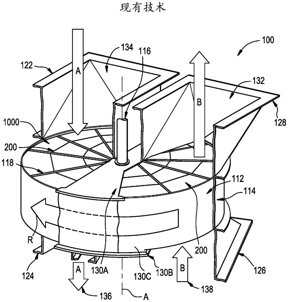
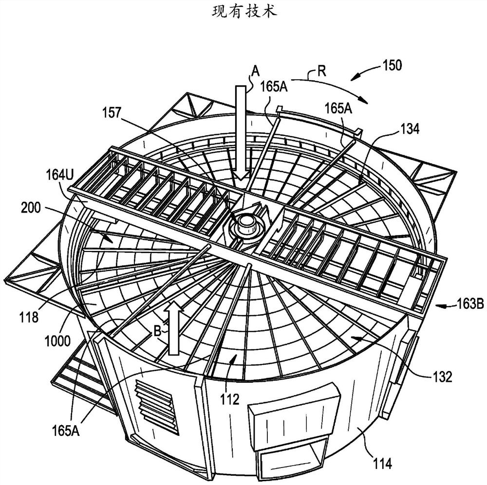
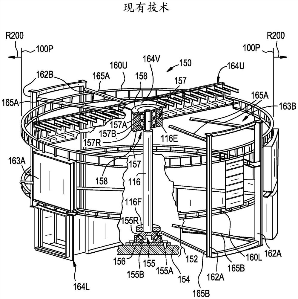
[0047] Such as Figure 4A As shown, the rotating regenerative heat exchanger 1 (see Figure 5A ) supporting structures are usually designated by the number 10. The support structure 10 is used to accommodate the rotor assembly 90 of the rotating regenerative heat exchanger 1 (see Figure 5A ) and for structural support and installation to foundations and piping ( Figure 12 piping system shown) of the exoskeleton. The support structure 10 is composed of an upper section 10U and a lower section 10L, which are axially spaced apart from each other along the central axis A and concentric with the central axis A, so that in the upper section 10U and the lower section An annular space S1 is defined between the segments 10L. Annular space S1 is configured to receive compartment 92 of rotor assembly 90, as referenced herein Figure 5A mentioned.

[0048] Such as Figure 4A As shown, the central axis A represents the vertical direction and thus the terms upper and lower are used...


PUM


Abstract

A support structure for a rotary regenerative heat exchanger is disclosed that includes an upper section, a lower section, and a plurality of support members. The upper section includes an upper ring having a first outer surface, an upper hub, and at least three upper spokes each extending between the upper ring and the upper hub and secured to the upper ring and the upper hub at respective ends of the upper spokes. Each support member of the plurality of support members is directly or indirectly securely secured to the upper ring and the lower section. An annular space is located between the upper and lower rings, the annular space configured to receive a compartment of a rotor assembly. The upper hub, the upper spokes, and the support members cooperate to provide stiffness to the support structure by cooperating to support the weight of the upper spokes, the upper ring, and the upper hub and to transfer the weight to the lower section.

Description

technical field [0001] The present invention generally relates to a low-profile support structure for a rotary regenerative heat exchanger suitable for carbon capture applications when its rotor is loaded with a structured sorbent configured to extract from Adsorbs carbon dioxide from warm air or flue gas and produces purified CO 2 and water vapor. Background technique [0002] Rotating regenerative heat exchangers (usually combustion air preheaters) are often used to transfer heat from the exhaust gas stream leaving a vessel (e.g., a furnace or chemical reactor) to the incoming air stream to enhance the process taking place in the vessel s efficiency. Conventional preheaters include a heat transfer sheet assembly comprising a plurality of heat transfer sheets stacked on top of each other in a basket. The heat transfer sheet absorbs heat from the exhaust gas flow and transfers this heat to the incoming air flow. The preheater also includes a rotor having radial partition...

Claims


Application Information

Patent Timeline
Patent Type & Authority Applications(China)
IPC IPC(8): F28D19/04F28F9/00F28F9/007
CPCF28D19/041F28D19/048F28F9/001F28F9/007Y02C20/40F28D19/042
Inventor W·J·小斯塔克A·C·索罗钦K·奥博伊尔
Owner ARVOS LJUNGSTROM LLC
Learn More