Cleaning device facilitating machine-made sand conveying belt

A technology for transmission belts and cleaning devices, which is applied in the direction of cleaning devices, transportation and packaging, and conveyor objects. It can solve problems such as belt deviation, damage, and belt surface retention, so as to facilitate removal or installation, avoid damage, and avoid running. Partial effect

Pending Publication Date: 2022-03-15
SINOHYDRO BUREAU 9
View PDF1 Cites 0 Cited by
  • Summary
  • Abstract
  • Description
  • Claims
  • Application Information

AI Technical Summary

Problems solved by technology

[0002] In the past ten years, the transmission belt has become an indispensable transmission tool for various production enterprises. With the use of the transmission belt, it will also bring a series of problems. During the production and operation of the belt conveyor, sticky materials will remain on the surface of the belt, and The design of the existing belt cleaning device is unreasonable. When sand, soil and other residues that are not easy to fall are attached to the surface during use, if the belt is not cleaned in time, problems such as deviation and damage of the belt will be caused, and the scraping of the existing cleaning device The plate is designed in one piece. When the residue that is not easy to scrape off on the belt interacts with the scraper, the scraper will be tilted, so that the lower position of the residue cannot be cleaned, and it may even cause the belt to deviate and be damaged. And other issues
For example, a belt cleaner disclosed in Chinese Patent Application No. CN202020008710.X, in which a pressing plate is arranged on the mounting shaft, and a scraper is arranged on the upper end of the pressing plate. It is easy to make the scraper tilt, and in serious cases, problems such as belt deviation and damage will occur

Method used


Image

  • Cleaning device facilitating machine-made sand conveying belt
  • Cleaning device facilitating machine-made sand conveying belt
  • Cleaning device facilitating machine-made sand conveying belt

Examples


Embodiment Construction

[0018] The technical solutions in the embodiments of the present invention are clearly and completely described below in conjunction with the accompanying drawings. Apparently, the described embodiments are only a part of the embodiments of the present invention, not all of them.

[0019] In describing the present invention, it should be understood that the terms "upper", "lower", "front", "rear", "left", "right", "top", "bottom", "inner", " The orientation or positional relationship indicated by "outside", etc. is based on the orientation or positional relationship shown in the drawings, and is only for the convenience of describing the present invention and simplifying the description, rather than indicating or implying that the referred device or element must have a specific orientation, so as to Specific orientation configurations and operations, therefore, are not to be construed as limitations on the invention.

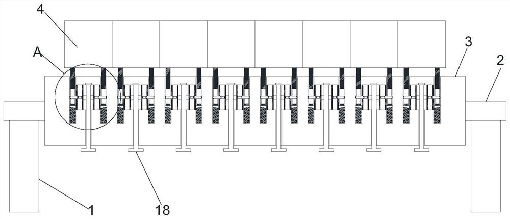
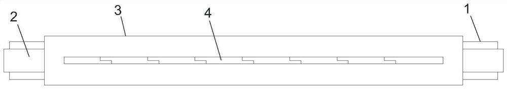
[0020] See attached Figure 1-4 , to facilitate the clean...


PUM


Abstract

A cleaning device facilitating a machine-made sand conveying belt comprises supporting rods arranged in a bilateral symmetry mode, supports are connected to the upper ends of the supporting rods, the close ends of the two supports are jointly connected with a scraping base, a plurality of scraping plates are evenly arranged above the scraping base in the length direction, inserting rods are connected to the lower end of each scraping plate in a bilateral symmetry mode, and inserting holes are formed in the scraping base. The bottom of the inserting hole is connected with a spring, the upper end of the spring is connected with an elastic plate, the inserting rod is movably connected in the inserting hole, the lower end of the inserting rod abuts against the upper surface of the elastic plate, and a connecting assembly allowing the inserting rod to move by a fixed distance is arranged on the scraping base. According to the cleaning device convenient for the machine-made sand conveying belt, the scraping plates are independent from one another, so that when residues which are not easy to scrape off on the belt act on the scraping plates, the phenomenon that the whole scraping plates incline is avoided, and the positions where the residues are low can be cleaned away relative to the residues which are not easy to scrape off; therefore, the problems of belt deviation, damage and the like are avoided.

Description

technical field [0001] The invention relates to the technical field of machine-made sand transmission belts, in particular to a cleaning device for machine-made sand transmission belts. Background technique [0002] In the past ten years, the transmission belt has become an indispensable transmission tool for various production enterprises. With the use of the transmission belt, it will also bring a series of problems. During the production and operation of the belt conveyor, sticky materials will remain on the surface of the belt, and The design of the existing belt cleaning device is unreasonable. When sand, soil and other residues that are not easy to fall are attached to the surface during use, if the belt is not cleaned in time, problems such as deviation and damage of the belt will be caused, and the scraping of the existing cleaning device The plate is designed in one piece. When the residue that is not easy to scrape off on the belt interacts with the scraper, the sc...

Claims


Application Information

Patent Timeline
IPC IPC(8): B65G45/16
CPCB65G45/16
Inventor 康刚杨劲松万林波张松黎旭严龙
Owner SINOHYDRO BUREAU 9
Why Eureka
Try Eureka