
Rotary clamping mechanism

A technology of clamping mechanism and rotating shaft, which is applied in the direction of grinding machine tool parts, metal processing equipment, grinding workpiece support, etc., and can solve the problems that cannot meet the demand

Active Publication Date: 2022-03-18
FUZHUN PRECISION TOOLING (JIASHAN) CO LTD
View PDF7 Cites 0 Cited by
  • Summary
  • Abstract
  • Description
  • Claims
  • Application Information

AI Technical Summary

Problems solved by technology

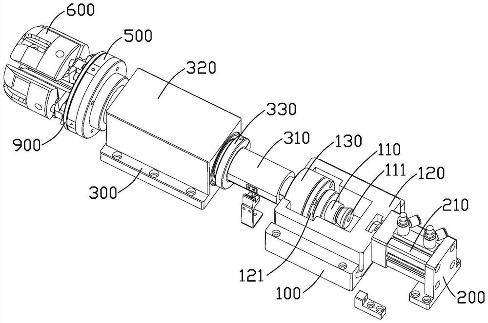
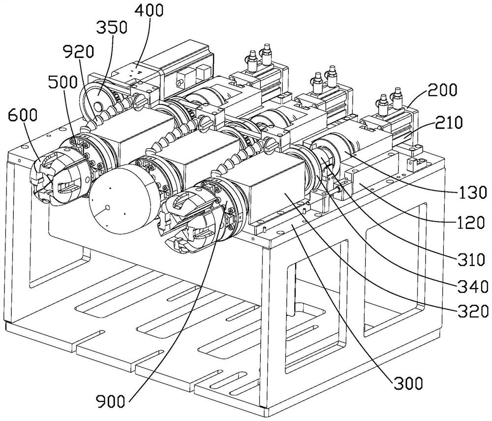
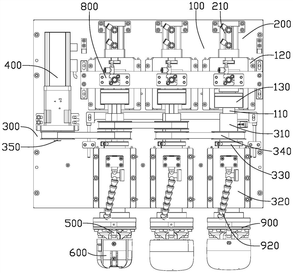
[0004] In view of the above, it is necessary to propose a rotary clamping mechanism to solve the problem that only opening and closing movement can be performed in the clamping equipment, but it cannot meet the demand when angle or position switching is required

Method used


Image

  • Rotary clamping mechanism
  • Rotary clamping mechanism
  • Rotary clamping mechanism

Examples


Embodiment Construction

[0053] In order to make the object, technical solution and advantages of the present invention clearer, the present invention will be further described in detail below in conjunction with the accompanying drawings and embodiments. It should be understood that the specific embodiments described here are only used to explain the present invention, not to limit the present invention. Based on the embodiments of the present invention, all other embodiments obtained by persons of ordinary skill in the art without making creative efforts belong to the protection scope of the present invention.

[0054] In describing the present invention, it should be understood that the terms "center", "longitudinal", "transverse", "length", "width", "thickness", "upper", "lower", "front", " Orientation or position indicated by "back", "left", "right", "vertical", "horizontal", "top", "bottom", "inside", "outside", "clockwise", "counterclockwise", etc. The relationship is based on the orientation ...


PUM


Abstract

The invention provides a rotary clamping mechanism which comprises a first transmission device, a second transmission device and a clamping device. The first driving device is connected with the first transmission device; the second transmission device comprises a rotating shaft connected to the telescopic column; the second driving device is connected with the second transmission device; the opening device comprises a connecting block and a plurality of sliding blocks, the connecting block is fixedly connected with the telescopic column, and the sliding blocks are connected to the connecting block in a sliding mode; and the multiple clamping jaws are fixedly connected with the multiple sliding blocks, and when the first driving device drives the telescopic column to move towards the clamping jaws, the multiple sliding blocks move away from the telescopic column on the connecting block in the direction perpendicular to the axial direction of the telescopic column, so that the multiple sliding blocks drive the multiple clamping jaws to be opened to clamp a workpiece. No spring component is used in the whole process, the whole is not prone to damage, and the service life is long. And meanwhile, in the clamping process, the rotating shaft is driven to rotate, so that the rotating shaft drives the telescopic column and the clamping jaw to rotate, rotation of the clamping jaw in the clamping process is achieved, and the clamping device adapts to various machining modes.

Description

technical field [0001] The invention relates to the technical field of clamping equipment, in particular to a rotary clamping mechanism. Background technique [0002] During the processing of the injection molding process, after the mold is closed, the surface of the injection molded workpiece will produce a mold line, which will affect the appearance of the product. Therefore, the outer surface of the final product needs to be polished to make the product surface smoother and more beautiful. [0003] During the grinding process, it is usually necessary to use a clamping device to clamp the workpiece, and then process the workpiece. However, when the clamping equipment in the prior art clamps the workpiece between multiple jaws, the multiple jaws can only perform opening and closing movement, but cannot meet the requirements when angle or position switching is required. Contents of the invention [0004] In view of the above, it is necessary to propose a rotary clamping m...

Claims


Application Information

Patent Timeline
Patent Type & Authority Applications(China)
IPC IPC(8): B24B41/06B24B41/00
CPCB24B41/06B24B41/00Y02P70/50
Inventor 姚云东匡奇赵振林夏稳进吴伟伟刘敏
Owner FUZHUN PRECISION TOOLING (JIASHAN) CO LTD
Learn More