Pixel circuit and display panel

A pixel circuit and potential technology, applied in static indicators, instruments, etc., can solve the problems of low luminous efficiency, multi-frequency division, uneven display, etc., to improve luminous efficiency, avoid excessive frequency division, and avoid uneven display Effect

Pending Publication Date: 2022-03-25
TCL CHINA STAR OPTOELECTRONICS TECH CO LTD
View PDF0 Cites 9 Cited by
  • Summary
  • Abstract
  • Description
  • Claims
  • Application Information

AI Technical Summary

Problems solved by technology

[0007] The present application provides a pixel circuit and a display panel to alleviate the technical problems of low luminous efficiency and uneven display in low-grayscale display, and the need for more frequency division in high-grayscale display

Method used


Image

  • Pixel circuit and display panel
  • Pixel circuit and display panel
  • Pixel circuit and display panel

Examples


Embodiment Construction

[0025] The technical solutions in the embodiments of the present application will be clearly and completely described below in conjunction with the drawings in the embodiments of the present application. Apparently, the described embodiments are only some of the embodiments of this application, not all of them. Based on the embodiments in this application, all other embodiments obtained by those skilled in the art without making creative efforts belong to the scope of protection of this application.

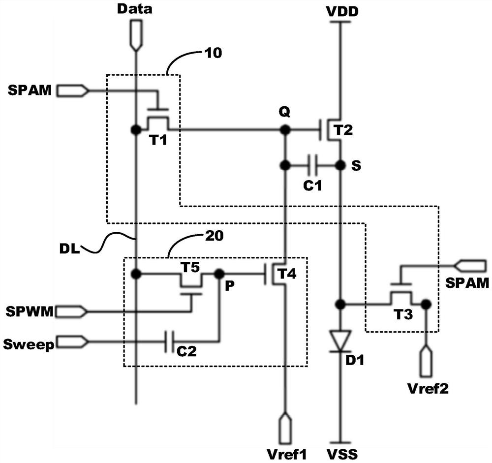
[0026] In view of the above-mentioned low luminous efficiency and uneven display in low-gray-scale display, and the technical problem that more frequency division is required in high-gray-scale display, this embodiment provides a pixel circuit. Please refer to Figure 3 to Figure 5 ,Such as image 3 As shown, the pixel circuit includes a driving transistor T2, a pulse width driving module 10, and a pulse width driving module 20. The pulse width driving module 10 is electrically ...


PUM


Abstract

The invention discloses a pixel circuit and a display panel, the pixel circuit comprises a driving transistor T2, a pulse amplitude driving module and a pulse width driving module, the pulse amplitude driving module drives the driving transistor T2 during high-gray-scale display in a frame, and excessive frequency division can be avoided during high-gray-scale display; and the pulse width driving module drives the driving transistor T2 during low-gray-scale display in one frame, so that the luminous efficiency can be improved and uneven display can be avoided during low-gray-scale display.

Description

technical field [0001] The present application relates to the field of display technology, in particular to a pixel circuit and a display panel. Background technique [0002] With the rapid development of display technology, display drive technology has also become one of the focuses of development. Among them, there are two common display drive technologies: PAM (Pulse Amplitude Modulation, pulse amplitude modulation) and PWM (PulseWidth Modulation, pulse width modulation) ,details as follows: [0003] Such as figure 1 The PAM driving technology shown achieves different luminances (Lv) by controlling the magnitude of the current (I). Its advantage is that the control method is simple; the disadvantage is that when the grayscale is low, that is, the current is low, the luminous efficiency of the light-emitting device is low, and the energy consumption is high. When the current is low, the brightness uniformity of the light-emitting device is poor, and it is prone to pittin...

Claims


Application Information

Patent Timeline
Patent Type & Authority Applications(China)
IPC IPC(8): G09G3/30G09G3/32G09G3/3225
CPCG09G3/30G09G3/32G09G3/3225G09G2320/0233
Inventor 徐健
Owner TCL CHINA STAR OPTOELECTRONICS TECH CO LTD
Why Eureka
Try Eureka