Clinical puncture device for cardiovascular medicine department

A cardiovascular and internal medicine technology, applied in the field of clinical puncture devices in cardiovascular internal medicine, can solve problems such as pain, difficulty in controlling angles, and limitations

Inactive Publication Date: 2022-03-29
郭孝兹
View PDF0 Cites 0 Cited by
  • Summary
  • Abstract
  • Description
  • Claims
  • Application Information

AI Technical Summary

Problems solved by technology

[0004] Aiming at the deficiencies of the prior art, the present invention provides a new type of clinical puncture device for cardiovascular medicine, which can adjust the height and angle of the device and limit the position of patients with different body shapes, so that the treatment can be performed more accurately It solves the difficulty of limiting the depth of puncture in the current market, and it is difficult for doctors to control the angle during cardiovascular clinical puncture. Due to the doctor's personal status and other reasons, deviations will occur during the puncture, and after deviations occur Cardiovascular puncture needs to be re-performed on the patient, causing psychological fluctuations and unnecessary pain to the patient, which may seriously cause massive pericardial hemorrhage. In addition, the device cannot perform multi-angle puncture so that the doctor needs to move the device to treat the patient. In the process, if the operation error makes the load-bearing device tilt, it will cause personal injury and the position of the patient cannot be limited for patients of different shapes, so that the device cannot be adjusted to a precise position for work, which will cause a series of problems in the later stage

Method used


Image

  • Clinical puncture device for cardiovascular medicine department
  • Clinical puncture device for cardiovascular medicine department
  • Clinical puncture device for cardiovascular medicine department

Examples


Embodiment Construction

[0023] The following will clearly and completely describe the technical solutions in the novel embodiments of the present invention in conjunction with the accompanying drawings in the novel embodiments of the present invention. Apparently, the described embodiments are only some of the novel embodiments of the present invention, rather than all of them. example. Based on the embodiments of the present invention, all other embodiments obtained by persons of ordinary skill in the art without making creative efforts belong to the protection scope of the present invention.

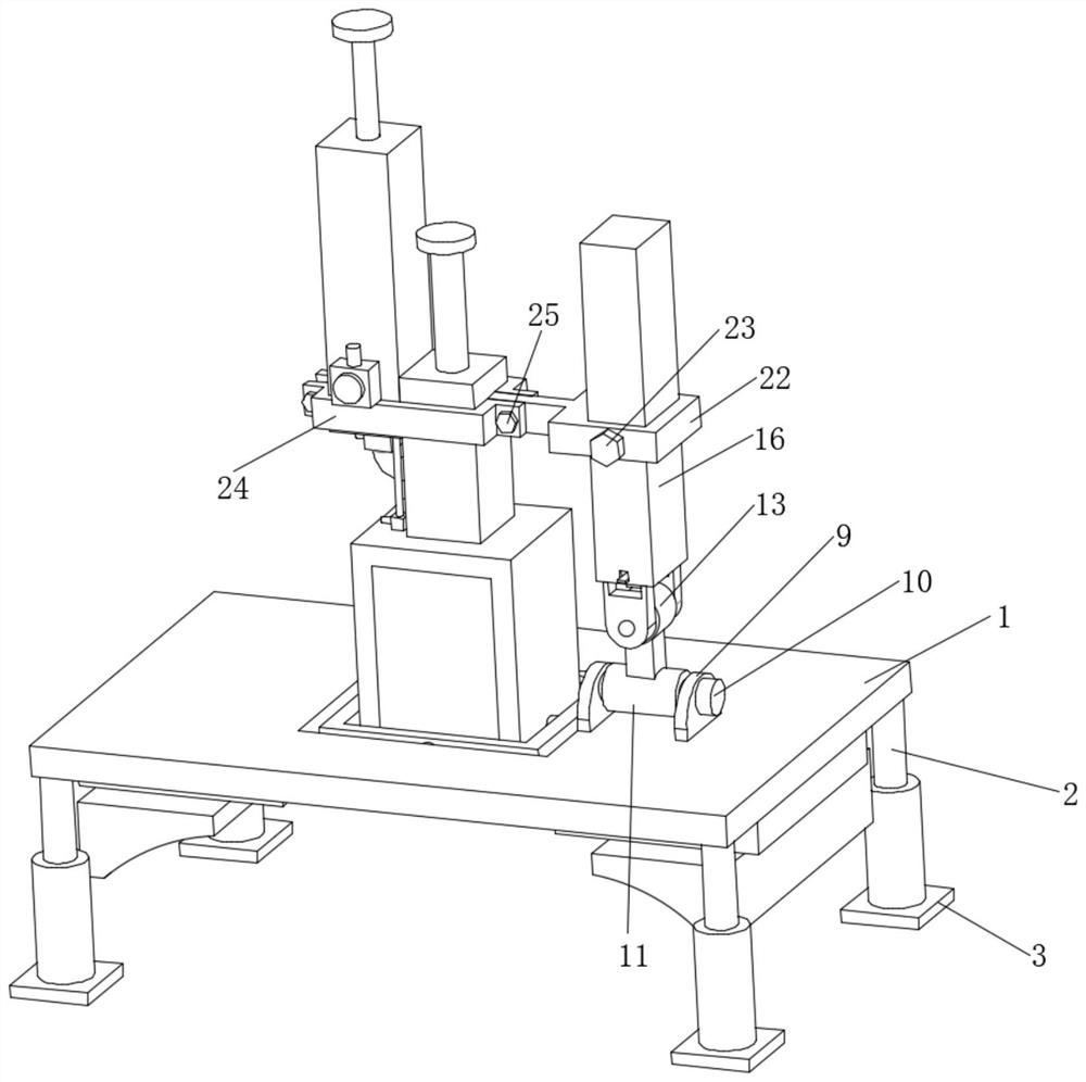
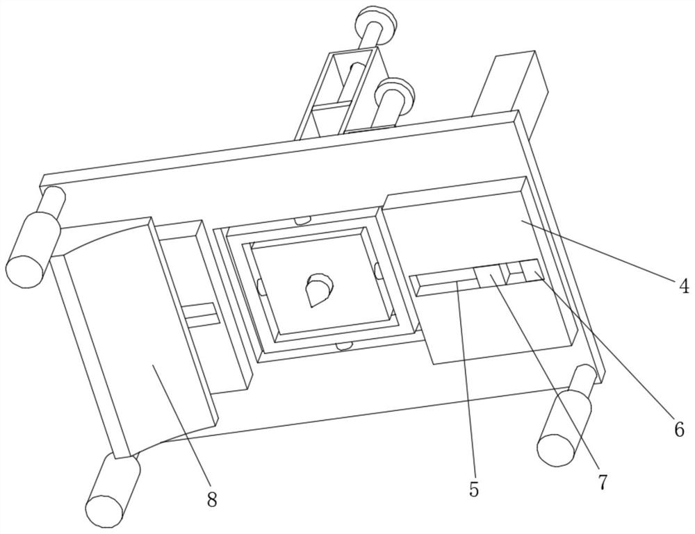
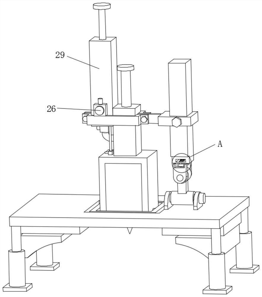
[0024] see Figure 1-6, a clinical puncture device for cardiovascular medicine, including a base plate 1, the bottom of the base plate 1 is fixedly installed with a telescopic rod 2, the device can be adjusted in height through the setting of the telescopic rod 2, and one end of the telescopic rod 2 is fixedly installed with a non-slip Pad 3, through the setting of the anti-slip pad 3, the position of the wh...


PUM


Abstract

The invention relates to the technical field of medical instruments, and discloses a clinical puncture device for the cardiovascular medicine department, which comprises a bottom plate, and a telescopic rod is fixedly mounted at the bottom of the bottom plate. According to the clinical puncture device for the cardiovascular medicine department, a first motor operates to drive a first rotating wheel to rotate so as to drive a stabilizing block to conduct angle adjustment, and the stabilizing block conducts angle adjustment to drive a second rotating wheel to operate so as to drive a first rotating shaft to rotate in a second supporting block; a shifting plate is shifted to drive a moving block to adjust the height so as to drive a clamping block to limit the position of the surface of a second rotating wheel, angle adjustment of a measuring ruler is driven by angle adjustment of a first rotating wheel and the second rotating wheel so as to drive height adjustment of an injection pipe, and angle adjustment of a rotating frame is driven by operation of a first rotating shaft; the puncture box is driven to conduct angle adjustment through operation of the second rotating shaft, the angle of the puncture body is adjusted through angle adjustment of the puncture box, and the problem that the puncture angle can be comprehensively adjusted is solved through the structure.

Description

technical field [0001] The invention relates to the technical field of medical devices, in particular to a clinical puncture device for cardiovascular medicine. Background technique [0002] Pericardiocentesis is a diagnosis and treatment technique that directly penetrates the pericardial cavity with the help of a puncture needle. Pericardiocentesis must be performed under aseptic technique, local application of procaine anesthesia, and the puncture site should not be too deep, so as not to puncture the atrium, ventricle or puncture the coronary artery A large amount of blood in the pericardial cavity is caused. Patients with pericardial puncture can understand the nature of pericardial effusion by testing the fluid in the pericardial cavity, and find out the cause of pericarditis according to the nature of pericardial effusion. Although pericardial puncture has certain risks, but If the operating procedures are strictly followed carefully, it is a relatively safe method of ...

Claims


Application Information

Patent Timeline
IPC IPC(8): A61B17/34
CPCA61B17/3403A61B2017/3405
Inventor 郭孝兹丁巍张利方
Owner 郭孝兹
Why Eureka
Try Eureka