Turnover horizontal type stone paint stirring machine

A mixer and stone paint technology, applied in mixer accessories, mixers, shaking/oscillating/vibrating mixers, etc., can solve the problems of inability to clean the stirring mechanism, difficult to clean the stirring mechanism, uneven mixing of real stone paint, etc.

Pending Publication Date: 2022-08-02
FOSHAN JUNGUANG MASCH CO LTD
View PDF1 Cites 0 Cited by
  • Summary
  • Abstract
  • Description
  • Claims
  • Application Information

AI Technical Summary

Problems solved by technology

[0004] 1. The stirring equipment is usually in the stirring position, so the stirring equipment can only stir the real stone paint in a fixed position, which leads to the uneven stirring of the real stone paint, which makes the stirring equipment unable to form left and right sliding and uniform stirring, and fully adjust the left and right inside the stirring equipment. Real stone paint is stirred;
[0005] 2. After the mixing equipment stirs the real stone paint, the real stone paint adheres to the surface of the mixing mechanism, and after the real stone paint solidifies, the surface of the mixing mechanism is difficult to clean, so that the mixing equipment cannot clean the surface of the stirring mechanism during the stirring process

Method used


Image

  • Turnover horizontal type stone paint stirring machine
  • Turnover horizontal type stone paint stirring machine
  • Turnover horizontal type stone paint stirring machine

Examples


Embodiment 1

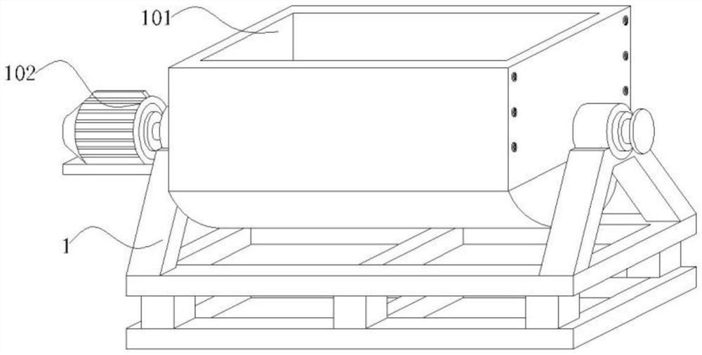
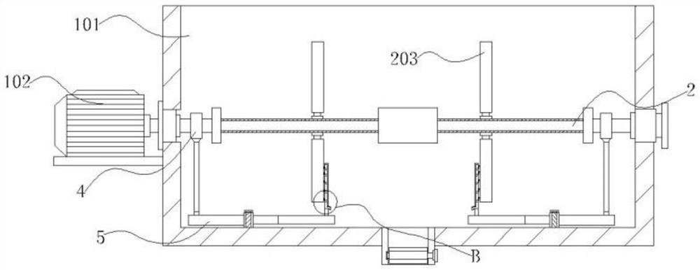
[0033] Embodiment 1: A reversible horizontal stone paint mixer, including a mixing device 1, a hopper 101 is installed on the upper end of the mixing device 1, a motor 102 is installed on one side of the hopper 101, and a side of the motor 102 close to the hopper 101 is rotatably connected with The roller shaft 202, the outer side of the roller shaft 202 slides and rotates with a stirring bracket 203, the outer side of the roller shaft 202 is provided with a transmission mechanism that can use centrifugal force to reciprocate stirring, and the two sides of the lower end of the hopper 101 are provided with inertial automatic cleaning of the stirring bracket 203. Scraping sliding mechanism;

[0034] Among them: the motor 102, the motor 102 is electrically connected with the power supply through the power cord, the side of the hopper 101 is equipped with a controller matched with the motor 102, and the roller shaft 202 rotates at a height on one side of the motor 102;

[0035] Th...

Embodiment 2

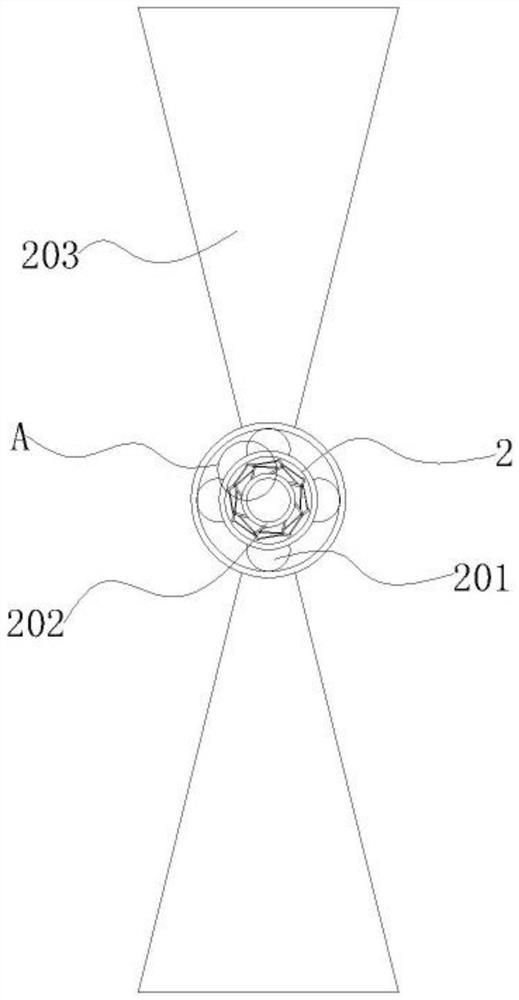
[0038] Example 2: Reference Manual Attached Figure 1-4 It can be seen that the difference between Embodiment 2 and Embodiment 1 is that the transmission mechanism includes an outer ring 2, a bump 201, a bracket 3, a rotating shaft 301, a swash plate 302 and a push rod 303, and the outer ring 2 is sleeved on the roller shaft 202. Outside, the bump 201 is embedded on the outside of the outer ring 2, the bracket 3 is embedded on the outside of the roller shaft 202, the rotating shaft 301 is hinged to one end of the support 3, the swash plate 302 swings at one end of the rotating shaft 301, and the push rod 303 is hinged to the end of the rotating shaft 301. The other side;

[0039] Wherein: the outer ring 2, the outer ring 2 penetrates and extends to the outside of the stirring support 203, the stirring support 203 slides on the outside of the outer ring 2, and the inside of the outer ring 2 is arranged in a hollow shape;

[0040] The bumps 201, the bumps 201 are arranged in a ...

Embodiment 3

[0046] Example 3: Reference Manual Attached Figure 5-7 It can be seen that the difference between Embodiment 3 and Embodiments 1 and 2 is that the sliding mechanism includes a collar 4, a shaft arm 401, a swing arm 5, a rotating bearing 501, a swing frame 502, a sliding rod 503, a scraper 504 and a discharge Tube 505, the collar 4 rotates on both sides of the roller shaft 202, the shaft arm 401 swings at one end of the collar 4, the swing arm 5, the rotating bearing 501 and the swing frame 502 swing on both sides of the lower end of the stirring device 1 in turn, and the sliding rod 503 slides on the upper end of the swing frame 502, the scraper 504 is embedded in the inner side of the sliding rod 503, and the discharge pipe 505 runs through one side of the sliding rod 503;

[0047] Wherein: the collar 4 and the axle arm 401, the end of the axle arm 401 away from the collar 4 is inclined 25-45°, and the end of the axle arm 401 away from the collar 4 is rotated and fitted with...


PUM


Abstract

The invention provides a turnover horizontal stone paint stirrer which comprises stirring equipment, a hopper is mounted at the upper end of the stirring equipment, a motor is mounted on one side of the hopper, a roll shaft is rotationally connected to the side, close to the hopper, of the motor, a stirring support is rotationally arranged on the outer side of the roll shaft in a sliding mode, and a transmission mechanism capable of conducting reciprocating stirring through centrifugal force is arranged on the outer side of the roll shaft. Sliding mechanisms for automatically cleaning and scraping the stirring support through inertia are arranged on the two sides of the lower end of the hopper, the motor is electrically connected with a power source through a power line, a controller matched with the motor is installed on one side of the hopper, and the roller shaft rotates at a high height on one side of the motor; wherein the push rod on one side of one group of inclined plates extrudes to one side of the other group of inclined plates, at the moment, the inclined plates are transiently disconnected with the outer ring, so that the outer ring stops rotating, the stirring bracket horizontally slides on the outer side of the outer ring due to inertia, and left-right uniform stirring is formed in the sliding process of the stirring bracket, so that the problem that when an existing stirrer is used for stirring, the stirring effect is poor is avoided. The position of the stirring mechanism is fixed.

Description

technical field [0001] The invention relates to the technical field of stone paint processing, in particular to a reversible horizontal stone paint mixer. Background technique [0002] Mixer is a professional equipment for producing real stone paint. Real stone paint is prepared with synthetic resin emulsion, colored sand particles of different grades and various additives. When processing real stone paint, a mixer needs to be used for stirring. Mixing, it is convenient to fully mix resin emulsion and colored sand particles, which is a technical inspiration for mixers; [0003] At present, CN202010963341.4 in the prior art is a comprehensive grinding linkage type real stone paint stirrer, which discloses a comprehensive grinding linkage type real stone paint stirrer. The invention solves the shortcomings of the existing vertical real stone paint stirrer, and the stirring effect is Obviously, and the stirring is uniform, the stirring rod will fully stir the real stone paint ...

Claims


Application Information

Patent Timeline
Patent Type & Authority Applications(China)
IPC IPC(8): B01F31/44B01F31/441B01F35/12B01F35/42B01F35/43
CPCB01F31/441B01F31/443B01F31/44B01F35/123B01F35/42B01F35/43B01F31/70Y02P70/10
Inventor 陈广明
Owner FOSHAN JUNGUANG MASCH CO LTD
Why Eureka
Try Eureka