Optical anti-shake structure, camera module with optical anti-shake structure and terminal equipment with optical anti-shake structure
An optical anti-shake, motion part technology, applied in image communication, parts of color TV, parts of TV system, etc., can solve problems such as affecting anti-shake performance, avoid magnetic interference, ensure performance, and expand application range effect
Pending Publication Date: 2022-03-29
BEIJING XIAOMI MOBILE SOFTWARE CO LTD
5 Cites 0 Cited by
AI-Extracted Technical Summary
Problems solved by technology
However, when the above-mentioned optical anti-shake structure is assembled in a mobile phone, the driving magnet in the optical anti...
View moreMethod used
In the present embodiment, the support member is a ball 320 structure, which not only can reduce the contact wear between the support member and the moving part 120, prolong the service life of both, but also make the movement of the moving part 120 on the support member It is relatively smooth and smooth, which helps to improve the imaging stability of the camera module.
In this embodiment, an image sensor 600 is accommodated in the accommodation area of the optical anti-shake structure, a drive motor 800 is installed on the carrier 100, a lens 900 is installed on the drive motor 800, and a gap between the lens 900 and the image sensor 600 A filter 700 is provided. The light sequentially passes through the lens 900 and the filter 700 to reach the image sensor 600 , and drives the image sensor 600 to move through the shape memory element to achieve optical image stabilization.
In this embodiment, the second shape memory element 220 connects the base part 110 and the moving part 120 and drives the moving part 120 to rotate around the third direction relative to the base part 110 during telescopic deformation, and then drives the image sensor 600 to follow the motion The parts 120 rotate synchronously. Wherein, the second shape memory member 220 can drive the moving part 120 to perform one-way rotation (clockwise or counterclockwise) or two-way rotation (clockwise and counterclockwise) around the third direction at the initial position, thus realizing The optical anti-shake in the rotation dimension improves the comprehensiveness of the optical anti-shake structure in the optical anti-shake function.
[0036] In this embodiment, the moving part 120 has an accommodating area for accommodating the image sensor 600 in the camera module. The moving part 120 is movable relative to the base part 110, and the moving part 120 drives the image sensor 600 to move to compensate for the offset of the imaging optical path caused by shaking and other reasons, so as to realize optical anti-shake, thereby improving the performance of the camera module in a moving state. The imaging quality and the imaging quality when shooting moving objects. The shape memory part is connected between the moving part 120 and the base part 110, and the shape memory part is used to drive the moving part 120 to move during telescopic deformation, which can avoid the use of driving magnets in the prior art, and further prevent the optical anti-shake structure from being assembled on the terminal, etc. When the device is installed, it will generate magnetic interference with other components with magnets, so as to ensure the performance of the optical anti-shake structure and other components with magnets. Especially when more than two camera modules are installed in the terminal device, the magnetic interference between the camera modules can be avoided, and the performance of each camera module can be ensured.
[0039] Wherein, the shape-memory element can drive the movement portion 120 to move relative to the base portion 110 by applying a driving force to the movement portion 120, so that the shape-memory element can directly act on the movement portion 120, which contributes to the anti-shake structure. Simplified structure.
[0058] Wherein, the rotation of the moving part 120 around the third direction may preferably be the rotation of the moving part 120 around the third direction, which can reduce the complexity of the optical anti-shake structure. Certainly, in other embodiments, the rotation of the moving part 120 around the third direction may be the revolution of the moving part 120 around the third direction.
[0060] In this embodiment, the second shape memory element 220 surrounds at least part of the moving part 120 along the circumferential direction of the moving part 120, which can increase the rotation angle of the moving part 120 and realize large-angle optical image stabilization in the rotation dimension. Please refer to FIG. 5 , taking the moving part 120 as a rectangle as an example, the second shape memory element 220 surrounds three adjacent sides of the moving part 120 , so that the moving part 120 has a relatively large rotation angle relative to the base part 110 .
[0063] In this embodiment, by recessing the accommodating groove 121 on the side of the moving part 120, the accommodating groove 121 can not only limit the position of the image sensor 600 located therein, but also reduce the movement of the moving part 120 and the image sensor. The overall thickness of the sensor 600 helps to thin the optical anti-shake structure and reduce the height of the camera module.
[0064] The accommodating groove is inclined relative to the moving part 120 along the direction opposite to the rotation direction of the moving part 120 under the action of the second shape memory member 220, so that the image sensor 600 located therein is in the same direction as the accommodating groove 121 relative to the moving part 120 Tilt setting. When the moving part 120 rotates at the initial position under the action of the second shape memory element 220 , the image sensor 600 can rotate from the initial position to the normalized position, which means that the image sensor 600 can rotate bidirectionally at the normalized position. In this way, the moving part 120 only needs to rotate in one direction at the initial position to achieve optical anti-shake in the rotational dimension, which helps to simplify the design and quantity of the second shape memory element 220 . Wherein, the straight position of the image sensor 600 may be a position parallel to the first direction or the second direction.
[0066] Of course, in other embodiments, two second shape memory elements 220 can be provided to respectively drive the moving part 120 to rotate positively and negatively around the third direction at the initial ...
View moreAbstract
The invention discloses an optical anti-shake structure, a camera module with the same and a terminal device, the optical anti-shake structure comprises a carrier, the carrier comprises a base body part and a moving part, the moving part is provided with an accommodating area for accommodating an image sensor, and the moving part is movably arranged relative to the base body part; the shape memory part is connected with the base body part and the moving part, and when the shape memory part stretches and deforms, the moving part moves relative to the base body part. According to the optical anti-shake structure, the camera module with the same and the terminal equipment provided by the invention, the image sensor is driven to move through the telescopic deformation of the shape memory part, so that an optical anti-shake function is realized, the imaging quality of the camera module in a moving state and the imaging quality of the camera module in shooting an object in the moving state are improved, and the imaging quality of the camera module in the moving state is improved. In addition, mutual magnetic interference with other parts with magnets can be avoided, and the use performance of the optical anti-vibration structure is ensured.
Application Domain
Technology Topic
Image
Examples
- Experimental program(1)
Example Embodiment
[0032] The present application will be further described in detail below with reference to the accompanying drawings and embodiments. It should be understood that the specific embodiments described herein are only used to explain the related invention, rather than limit the invention. In addition, it should be noted that, for the convenience of description, only the parts related to the invention are shown in the drawings.
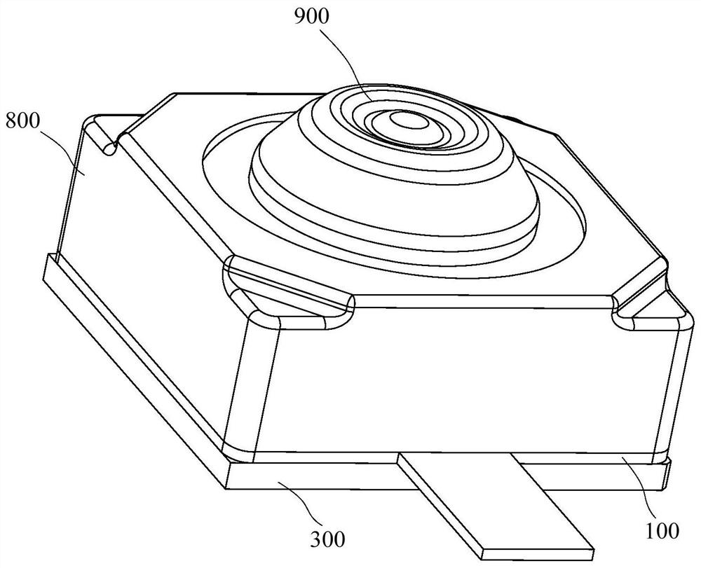
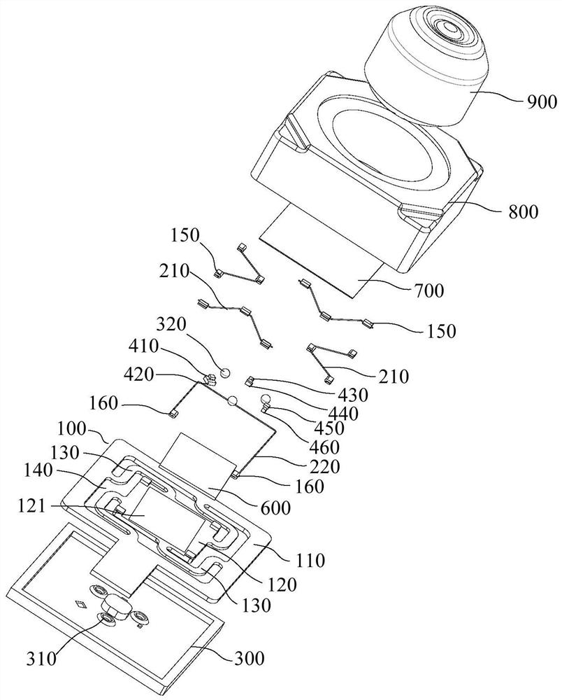
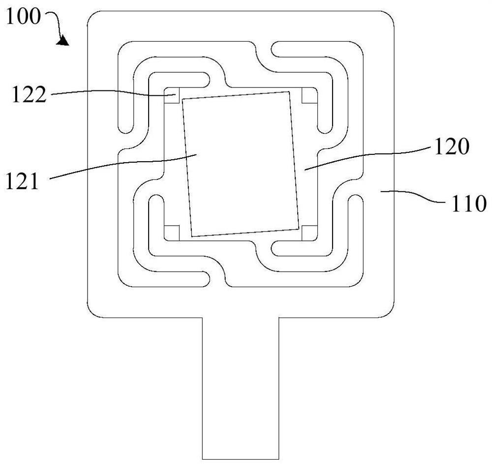
[0033] Please refer to the attached Figure 1-3 , the embodiment of the present application provides an optical anti-shake structure, including:
[0034] The carrier 100, the carrier 100 includes a base part 110 and a moving part 120, the moving part 120 has an accommodating area for accommodating the image sensor 600, and the moving part 120 is movably arranged relative to the base part 110;
[0035] The shape memory element connects the base part 110 and the moving part 120 , and when the shape memory element is stretched and deformed, the moving part 120 moves relative to the base part 110 .
[0036] In this embodiment, the moving part 120 has an accommodating area, and the accommodating area is used for accommodating the image sensor 600 in the camera module. The moving part 120 is movable relative to the base part 110, and the moving part 120 drives the image sensor 600 to move, so as to compensate for the deviation of the imaging optical path caused by jitter and other reasons, and realize optical anti-shake, thereby improving the camera module in the moving state. image quality and image quality when shooting moving objects. A shape memory element is connected between the moving part 120 and the base part 110, and the shape memory element is used to drive the moving part 120 to move during telescopic deformation, which can avoid the use of driving magnets in the prior art, and thus avoid the optical anti-shake structure being assembled in terminals, etc. When the device and other parts with magnets generate mutual magnetic interference, the optical anti-shake structure and the use performance of other parts with magnets are ensured. Especially when more than two camera modules are assembled in the terminal device, the magnetic interference between the camera modules can be avoided, and the use performance of each camera module can be ensured.
[0037] Since the force generated by the shape memory element during the telescopic deformation is greater than the driving force of the driving magnet in the prior art, it can drive the image sensor 600 with a large weight, thereby realizing optical image stabilization in a high-pixel and heavy-weight camera module. , which expands the scope of application of the optical anti-shake structure and improves the practicability of the optical anti-shake structure.
[0038] Wherein, the shape memory member can be expanded and deformed when the temperature changes. Of course, the conditions for realizing the expansion and contraction of the shape memory member are not limited to the above temperature changes.
[0039] The shape memory element can drive the motion part 120 to move relative to the base part 110 by applying a driving force to the motion part 120 . This arrangement enables the shape memory element to directly act on the motion part 120 , which is helpful for simplifying the structure of the anti-shake structure.
[0040] In some embodiments of the present application, the shape memory member includes a first shape memory member 210 . The first shape memory member 210 connects the base portion 110 and the moving portion 120 . When the first shape memory member 210 is stretched and deformed, the moving portion 120 is opposite to each other. The base portion 110 moves in translation along the target direction.
[0041] In this embodiment, the moving part 120 is moved relative to the base part 110 in translation along the target direction under the driving of the first shape memory member 210 , which can realize the optical anti-shake of the camera module in the target direction. The target direction includes but is not limited to one direction or two or more different directions, and is also not limited to a linear translation direction or a rotation direction.
[0042] Please refer to the attached Figure 4 , in some embodiments of the present application, the target direction includes the first direction and/or the second direction, when the target direction includes the first direction and the second direction, the number of the first shape memory elements 210 is two or more, wherein When a part of the first shape memory members 210 are telescopically deformed, the moving part 120 moves in translation relative to the base part 110 in the first direction, and when another part of the first shape memory members 210 is telescopically deformed, the moving part 120 moves relative to the base part 110 translates and moves along a second direction, and the first direction and the second direction are perpendicular.
[0043]In this embodiment, the target direction includes a first direction, and the movement portion 120 is driven to move in translation along the first direction relative to the base portion 110 by the expansion and contraction of the first shape memory member 210 ; or, the target direction includes a second direction, through the first The telescopic deformation of the shape memory member 210 drives the moving portion 120 to move in translation relative to the base portion 110 along the second direction; or, the target direction includes the first direction and the second direction, and at this time, two moving portions are connected between the moving portion 120 and the base portion 110 The above-mentioned first shape memory members 210 drive the moving portion 120 to move in translation relative to the base portion 110 in the first direction through the expansion and contraction of a part of the first shape memory members 210 , and through the expansion and contraction of another part of the first shape memory members 210 . The telescopic deformation drives the moving part 120 to move in translation along the second direction relative to the base part 110 . This arrangement enables the moving part 120 to move relative to the base part 110 in translation along the first direction and the second direction, that is, the image sensor 600 can move along with the moving part 120 along the first and second directions. It can be moved in two mutually perpendicular directions, so that the optical image stabilization of the camera module in the mutually perpendicular first and second directions can be realized, which improves the comprehensiveness of the optical image stabilization structure in the optical image stabilization function. sex.
[0044] Wherein, when the target direction includes the first direction or the second direction, the number of the first shape memory elements 210 may be one or more than two. The first direction can be unidirectional or bidirectional, and the second direction can also be unidirectional or bidirectional. When the first direction is bidirectional, the first shape memory member 210 can drive the moving part 120 to move and reset in translation along the first direction; when the second direction is bidirectional, the first shape memory member 210 can drive the moving part 120 to move along the second direction Orientation translation move and reset.
[0045] The present application does not limit the specific directions of the first direction and the second direction. The first direction and the second direction include but are not limited to: the first direction is the length direction of the carrier 100, and the second direction is the width direction of the carrier 100. For details, please refer to the appendix Figure 4 The middle direction A is the first direction and the direction B is the second direction; or, the first direction is the width direction of the carrier 100 , and the second direction is the length direction of the carrier 100 .
[0046] In some embodiments of the present application, the moving part 120 is provided with first shape memory members 210 on both sides along the target direction.
[0047] In this embodiment, the moving part 120 is provided with first shape memory members 210 on both sides along the target direction, and the first shape memory members 210 on both sides are used to drive the moving part 120 to the initial position along the target direction. The translation movement on both sides can realize optical image stabilization in the target dimension where the target direction is located. The initial position of the moving part 120 should be understood as the position where the moving part 120 is located when there is no optical shake, for example, the attachment Figure 4 location shown.
[0048] When the target direction is the first direction, the moving part 120 is provided with first shape memory members 210 on both sides along the first direction, and the first shape memory members 210 on both sides are used to drive the moving part 120 to the initial position at The translational movement along both sides of the first direction realizes optical anti-shake in the first translation dimension to which the first direction belongs. When the target direction is the second direction, the moving portion 120 is provided with first shape memory members 210 on both sides along the second direction, and the second shape memory members 210 on both sides are used to drive the moving portion 120 to the initial position at The translational movement along both sides of the second direction realizes optical anti-shake in the second translation dimension to which the second direction belongs. When the target direction is the first direction and the second direction, the moving part 120 is provided with the first shape memory element 210 on both sides along the first direction and the first shape memory element 210 is also provided on both sides along the second direction The first shape memory members 210 located on both sides of the moving part 120 in the first direction are used to drive the moving part 120 to move to the initial position in translation on both sides along the first direction, and the first shape memory parts 210 located on both sides of the moving part 120 in the second direction The first shape memory member 210 is used to drive the moving part 120 to move in translation on both sides along the second direction to the initial position, realize the optical anti-shake in the first translation dimension and the second translation dimension, and improve the optical anti-shake structure. Comprehensive optical image stabilization. Wherein, the first translation dimension and the second translation dimension are perpendicular to each other.
[0049] For example: please refer to the appendix Figure 4 , the moving part 120 is provided with a first shape memory member 210 on both sides along the first direction. The first shape memory element 210 on the side can drive the moving part 120 to move in translation to the right along the first direction at the initial position.
[0050] In some embodiments of the present application, the moving portion 120 has at least one first connection location, the base portion 110 has at least one second connection location, and a first shape memory member 210 is connected to the at least one first connection location and the at least one first connection location. two connection positions;
[0051] Wherein, the figure formed by the connecting line of at least one first connection position and at least one second connection position is a symmetrical figure, and the symmetry axis of the symmetrical figure is parallel to the target direction.
[0052] In the present embodiment, the carrier 100 may be jointly connected to a first shape memory member 210 through at least one first connection position on the moving part 120 and at least one second connection position on the base part 110 , wherein the at least one first connection position The figure formed by the line connecting the at least one second connection position is a symmetrical figure, and the symmetry axis of the symmetrical figure is parallel to the target direction, so that the first shape memory element 210 connected to the first connection position and the second connection position can be located in the target direction. The direction of the acting force provided to the moving part 120 during the telescopic deformation is parallel to the target direction, so as to drive the moving part 120 to move accurately along the target direction.
[0053] For example, the moving part 120 is provided with a first connection position, the base part 110 is provided with two second connection positions, and the figure formed by the connection of the first connection position and the two second connection positions is an isosceles trapezoid, such as attached Figure 4 Alternatively, the moving part 120 is provided with two first connection positions, the base part 110 is provided with a second connection position, and the figure formed by the connection of the two first connection positions and the second connection position is isosceles trapezoid. For another example, the moving part 120 is provided with a first connection position, the base part 110 is provided with a second connection position, and the figure formed by the connection between the first connection position and the second connection position is a rectangle.
[0054] Wherein, when the first shape memory member 210 connected to the first connection position and the second connection position drives the moving part 210 to translate and move in the first direction, the symmetry axis of the symmetrical figure is parallel to the first direction; When the first shape memory member 210 at the connection position and the second connection position drives the moving part 210 to translate and move in the second direction, the symmetry axis of the symmetrical figure is parallel to the second direction.
[0055] Wherein, when two or more first shape memory members 210 are connected between the moving portion 120 and the base portion 110, the moving portion 120 and the base portion 110 can be connected with each first shape memory member in the same connection manner as above. 210, so that the processing efficiency of the anti-shake module can be improved. as attached Figure 4 As shown, the four first shape memory elements 210 connected between the moving part 120 and the base part 110 all adopt the above-mentioned connection manner. Of course, in other embodiments, the moving part 120 and the base part 110 may adopt different connection manners to connect more than two first shape memory members 210 . For example: when two first shape memory members 210 are connected between the moving part 120 and the base part 110, at least one first connection position and at least one second connection position for connecting one of the first shape memory members 210 are connected. The image formed by the line is an isosceles trapezoid, and the image formed by connecting the at least one first connection position and the at least one second connection position of the other first shape memory element 210 is a rectangle or the like.
[0056] Please refer to the attached Figure 5 , in some embodiments of the present application, the deformation memory member further includes a second shape memory member 220, the second shape memory member 220 is connected to the base portion 110 and the moving portion, and when the second shape memory member 220 is telescopically deformed, the moving portion 120 Relative to the base portion 110 to rotate around a third direction, the first direction, the second direction and the third direction are perpendicular to each other.
[0057] In this embodiment, the second shape memory member 220 connects the base portion 110 and the moving portion 120 , and drives the moving portion 120 to rotate in a third direction relative to the base portion 110 during telescopic deformation, thereby driving the image sensor 600 to synchronize with the moving portion 120 . rotate. Wherein, the second shape memory member 220 can drive the moving part 120 to rotate unidirectionally (clockwise or counterclockwise) or bidirectionally (clockwise and counterclockwise) around the third direction at the initial position. The optical image stabilization in the rotation dimension improves the comprehensiveness of the optical image stabilization structure in the optical image stabilization function.
[0058] The rotation of the moving part 120 around the third direction may preferably be the rotation of the moving part 120 around the third direction, which can reduce the complexity of the optical anti-shake structure. Of course, in other embodiments, the rotation of the moving part 120 around the third direction may be the revolving of the moving part 120 around the third direction.
[0059] In some embodiments of the present application, the second shape memory member 220 is disposed circumferentially around at least part of the moving portion 120 .
[0060] In this embodiment, the second shape memory member 220 surrounds at least part of the moving portion 120 in the circumferential direction of the moving portion 120 , which can increase the rotation angle of the moving portion 120 and realize large-angle optical image stabilization in the rotational dimension. Please refer to the attached Figure 5 Taking the moving part 120 as a rectangle as an example, the second shape memory element 220 surrounds three adjacent sides of the moving part 120 , so that the moving part 120 has a relatively large rotation angle relative to the base part 110 .
[0061] It should be understood that the rotation angle of the moving portion 120 relative to the base portion 110 may depend on the length of the portion of the second shape memory member 220 surrounding the moving portion 120 in the circumferential direction, when the second shape memory member 220 circumferentially surrounds the moving portion 120 The longer the length of the portion of the moving portion 120 , that is, the more the second shape memory member 220 surrounds the moving portion 120 in the circumferential direction, the greater the rotational angle of the moving portion 120 in the clockwise or counterclockwise direction.
[0062] In some embodiments of the present application, the accommodating area is an accommodating groove 121 recessed in the moving part 120 , and the accommodating groove is opposite to the rotating direction of the moving part 120 under the action of the second shape memory member 220 relative to the moving part 120 . Orientation tilt setting.
[0063] In this embodiment, by concavely providing the accommodating groove 121 on the side surface of the moving part 120 , the accommodating groove 121 can not only limit the position of the image sensor 600 located therein, but also reduce the distance between the moving part 120 and the image sensor 600 . The overall thickness helps to thin the optical anti-shake structure and reduce the height of the camera module.
[0064] The accommodating groove is inclined relative to the moving part 120 in the opposite direction to the rotation direction of the moving part 120 under the action of the second shape memory member 220 , so that the image sensor 600 located therein is inclined relative to the moving part 120 and the accommodating groove 121 in the same direction. When the moving part 120 rotates at the initial position under the action of the second shape memory member 220 , the image sensor 600 can rotate from the initial position to the corrected position, that is, the image sensor 600 can rotate bidirectionally at the corrected position. In this way, the moving part 120 only needs to rotate in one direction at the initial position to realize the optical anti-shake in the rotation dimension, which helps to simplify the design and quantity of the second shape memory elements 220 . The straightened position of the image sensor 600 may be a position parallel to the first direction or the second direction.
[0065] Based on the attached Figure 5 As shown, the second shape memory member 220 can drive the moving part 120 to rotate in a clockwise direction, the accommodating groove 121 is inclined in a counterclockwise direction relative to the moving part 120, and the correct position of the accommodating groove 121 is parallel to the first direction. Location.
[0066]Of course, in other embodiments, two second shape memory members 220 are provided to drive the moving part 120 to rotate forward and reverse around the third direction at the initial position respectively, so as to realize the optical image stabilization in the rotation dimension.
[0067] It should be understood that, when the image sensor 600 is in an initial position, it is inclined relative to the straightened position, and the camera module can perform anti-shake compensation through electronic anti-shake and other methods. The initial position of the image sensor 600 is the position of the moving part 120 in the initial position.
[0068] In some embodiments of the present application, the first shape memory member 210 is a flexible structure, and the length of the first shape memory member 210 is shortened when the power is heated up to drive the moving part 120 to move; and/or the second shape memory member 220 is a Flexible structure, and the length of the second shape memory element 220 is shortened when the power is heated up to drive the moving part 120 to rotate.
[0069] In this embodiment, the first shape memory member 210 is a flexible structure, so that the first shape memory member 210 can be bent and straightened. Similarly, the second shape memory member 220 is a flexible structure, so that the second shape memory member 220 can be bent and straightened. The first shape memory member 210 and/or the second shape memory member 220 is a flexible structure, and it should be understood that the shape memory member is a flexible structure in a state when there is no temperature change to stretch and deform, that is, the shape memory member is flexible in a natural state. structure. When the first shape memory member 210 and/or the second shape memory member 220 is stretched and deformed under a temperature change, its structure may be flexible or rigid.
[0070] When the first shape memory element 210 is energized, the temperature of the first shape memory element 210 will increase due to the existence of the internal resistance, and at this time, the length of the first shape memory element 210 will be shortened. When the length of the first shape memory element 210 is shortened, it will drive the moving part 120 to move, that is, the first shape memory element 210 pulls the moving part 120 toward it; when the first shape memory element 210 is powered off and the temperature drops, the A shape memory device 210 performs shape recovery. Similarly, when the second shape memory element 220 is energized, the temperature of the second shape memory element 220 will increase due to the existence of the internal resistance, and at this time, the length of the second shape memory element 220 will be shortened. When the length of the second shape memory element 220 is shortened, the moving part 120 is driven to rotate, that is, the second shape memory element 220 pulls the moving part 120 toward it; when the second shape memory element 220 is powered off and the temperature drops, the first The shape of the two shape memory elements 220 is restored.
[0071] The shapes of the first shape memory member 210 and the second shape memory member 220 include but are not limited to filament shape memory alloys, which are not limited in the present application.
[0072] Of course, in other embodiments, the first shape memory member 210 and/or the second shape memory member 220 may expand and contract when heated to drive the moving part 120 to move, and retract after warming to drive the moving part 120 to reset.
[0073] In some embodiments of the present application, the portion of the first shape memory member 210 between the connection positions connected to the base body 110 and the moving portion 120 has a curved first margin segment; and/or, the second shape memory The part of the member 220 between the connection positions connected with the base part 110 and the moving part 120 has a curved second margin section.
[0074] In this embodiment, when the first shape memory member 210 and the second shape memory member 220 are both flexible structures and the length is shortened when the power is heated up, the first shape memory member 210 is provided with a first margin section and a The second shape memory member 220 is provided with a second margin section, so that the moving part 120 can move a required distance in the first direction or the second direction under the driving of some of the first shape memory members 210, and during the movement process It will not be restricted by the pulling of the other first shape memory member 210 or the second shape memory member 220, and at the same time, the moving part 120 can be rotated by the required angle under the driving of the second shape memory member 220, and during the rotation process It is not limited by the pulling of the first shape memory member 210 . Wherein, when the moving part 120 moves in the first direction or the second direction driven by some of the first shape memory elements 210 , the margin segments in the remaining first shape memory elements 210 and the second shape memory elements 220 will gradually shrink or even disappear; when the moving part 120 is rotated under the driving of the second shape memory element 220 , the margin segment in the first shape memory element 210 will gradually shrink or even disappear.
[0075] The lengths of the first margin segment and the second margin segment can be set according to usage requirements, thereby realizing large-angle optical image stabilization in two moving dimensions.
[0076] Of course, in other embodiments, when the first shape memory member 210 is a flexible structure and the length is shortened when the power is heated up, the second shape memory member 220 may also be a flexible structure and expand and contract relative to the initial length when the temperature changes; or , when the second shape memory member 220 is a flexible structure and the length is shortened when the power is heated up, the first shape memory member 210 can also be a flexible structure and expand and contract relative to the initial length when the temperature changes, so as to meet the above-mentioned dimensions of the moving part 120 The need for distance or angle of movement.
[0077] In some embodiments of the present application, an elastic part is connected between the moving part 120 and the base part 110 , and the elastic part stores elastic potential energy when the moving part 120 moves, and the stored elastic potential energy is used to drive the moving part 120 to reset.
[0078] In this embodiment, the elastic part can be used to drive the moving part 120 to automatically reset after the movement, so that the shape memory device does not need to select a type with the functions of driving the moving part 120 to move and reset, which helps to increase the use options of the shape memory device range and reduce the number of shape memory devices used. For example, the shape memory member may be of a type that is flexible and shortens in length when heated, and a single shape memory member of this type can drive the moving part 120 to move, but cannot drive the moving part 120 to reset.
[0079] When the shape memory element drives the moving part 120 to move, the moving part 120 drives the elastic part to deform to store a certain elastic potential energy, and when the shape memory element recovers the shape, the stored elastic potential energy is released to drive the moving part 120 to automatically perform reset.
[0080] Of course, in other embodiments, the moving part 120 is driven to reset by the shape memory element when the shape is restored, or the moving part 120 is driven to reset by using other shape memory elements.
[0081] In some embodiments of the present application, the base part 110 has a through opening part, and the moving part 120 is located in the opening part. This arrangement can reduce the thickness of the overall structure formed by the base part 110 and the moving part 120 , which is helpful for reducing the thickness of the optical anti-shake structure and reducing the height of the camera module.
[0082] In some embodiments of the present application, the carrier 100 is a flexible circuit board, and the flexible circuit board includes:
[0083] the first part, the first part forms the moving part 120;
[0084] the second part, the second part is arranged around the outer periphery of the first part, and the second part forms the base part 110;
[0085] At least one connecting part 130 is located between the first part and the second part, the connecting part 130 is bent and connects the first part and the second part, and the at least one connecting part 130 forms an elastic part.
[0086] In this embodiment, the carrier 100 adopts a flexible circuit board structure, and the flexible circuit board may include a first part, a second part and at least one connection part 130 . The second part surrounds the outer circumference of the first part with a space therebetween, at least one connecting part 130 is located in the space and each connecting part 130 connects the first part and the second part. The connecting portion 130 is a flexible circuit board and is bent so that the connecting portion 130 has a certain elasticity. The first part can be used as the moving part 120, the second part can be used as the base part 110, the at least one connecting part 130 can be used as the elastic part, and both the first part and the at least one connecting part 130 are located in the opening of the second part.
[0087] The external circuit of the image sensor 600 and the power supply circuit of the shape memory device can be directly formed on the flexible circuit board structure without configuring an additional circuit board, which helps to simplify the structure of the camera module. It should be understood that the connecting portion 130 can not only serve as an elastic portion, but also be used for wiring to form the above-mentioned power supply circuit and the like.
[0088] In some embodiments of the present application, the elastic portion includes two or more connecting portions 130 , and the two or more connecting portions 130 are arranged at intervals along a peripheral direction surrounding the first portion.
[0089] In this embodiment, the elastic portion includes more than two connecting portions 130, and the two or more connecting portions 130 are arranged at intervals along the outer circumferential direction of the first portion, so that the force of the moving portion 120 is more uniform, and the movement of the moving portion 120 is improved. The smoothness of the reset movement.
[0090] In some embodiments of the present application, the first part, the second part and the at least one connecting part 130 are in an integrated structure, wherein any two adjacent connecting parts 130 are separated by a hollow part 140 at intervals. This arrangement can facilitate the processing of the carrier 100 .
[0091] The processing process of the carrier 100 includes, but is not limited to, the carrier 100 of the present embodiment can be processed by opening the hollow portion 140 on the prefabricated flexible circuit board.
[0092] In some embodiments of the present application, the optical anti-shake structure further includes a mount 300 , the mount 300 is located on a side of the carrier 100 away from the accommodating area, the carrier 100 is mounted on the mount 300 between the mount 300 and the moving part 120 A plurality of support members are provided, and the plurality of support members support and cooperate with the moving portion 120 , wherein the plurality of support members are not parallel and are arranged flush with one end away from the mounting seat 300 .
[0093] In this embodiment, the mounting seat 300 is located on a side of the carrier 100 away from the accommodating area, and is used for carrying the mounting carrier 100 . A plurality of support members are disposed between the mounting base 300 and the moving portion 120 , and the plurality of support members are used to jointly support the moving portion 120 . Wherein, the plurality of supports are not arranged in parallel and are arranged flush with one end away from the mounting seat 300 , that is, one end of the plurality of supports away from the mounting seat 300 together forms a support plane, so that the moving portion 120 is formed on the plurality of supports. The support plane can move smoothly and can be kept parallel to the support plane during movement, thereby ensuring the positional relationship between the lens 900 and the image sensor 600 and ensuring image quality.
[0094] In some embodiments of the present application, the supporting member is a ball 320 , and one end of the mounting base 300 close to the moving part 120 or one end of the moving part 120 close to the mounting base 300 is provided with a plurality of positioning grooves 310 , and the plurality of balls 320 are respectively installed in the multiple positioning grooves 310 . There are positioning grooves 310 , and the balls 320 are positioned and matched with the corresponding positioning grooves 310 .
[0095] In this embodiment, the support member is a ball 320 structure, which can not only reduce the contact wear between the support member and the moving part 120 and prolong the service life of the two, but also make the movement of the moving part 120 on the support member relatively smooth and smooth. , which helps to improve the imaging stability of the camera module.
[0096] One end of the mounting seat 300 close to the moving part 120 or one end of the moving part 120 close to the mounting seat 300 is provided with a plurality of positioning grooves 310 , the plurality of balls 320 are respectively installed in the plurality of positioning grooves 310 , and the balls 320 are positioned and matched with the corresponding positioning grooves 310 , the ball 320 can be prevented from moving between the mounting seat 300 and the carrier 100 . Wherein, the positioning groove 310 may preferably be disposed on the mounting seat 300 to facilitate the assembly between the carrier 100 , the mounting seat 300 and the ball 320 .
[0097]In addition, a plurality of movable grooves 123 are recessed on the side of the moving portion 120 close to the mounting seat 300 , and the plurality of movable grooves 123 are arranged in a one-to-one correspondence with the plurality of positioning grooves 310 , and the end of the ball 320 away from the positioning groove 310 is located in the corresponding movable groove 123 , In order to reduce the overall thickness between the mounting seat 300 and the carrier 100 . The balls 320 and the movable grooves 123 are in clearance fit to prevent the balls 320 from restricting the movement of the moving part 120 .
[0098] In some embodiments of the present application, the connecting positions of the moving portion 120 and the base portion 110 and the first shape memory member 210 are provided with conductive first clamping members 150 , and the first clamping members 150 are used to clamp the first conductive member 150 . A shape memory member 210; the connecting positions of the moving portion 120 and the base portion 110 and the second shape memory member 220 are provided with conductive second clamping members 160, and the second shape memory member 160 is used to clamp the second shape memory member Piece 220.
[0099] In this embodiment, the carrier 100 is connected to the first shape memory member 210 through the first clamping member 150 , so that the first shape memory member 210 can connect the first clamping member 150 and the carrier 100 when the first shape memory member 210 is stretched and deformed. The influence of strength is small, and the connection strength and stability between the first shape memory element 210 and the carrier 100 are ensured. The carrier 100 is connected to the second shape memory member 220 through the second clamping member 160, so that the second shape memory member 220 has little influence on the connection strength between the second clamping member 160 and the carrier 100 when the second shape memory member 220 is stretched and deformed, and ensures the first The strength and stability of the connection between the shape memory member 220 and the carrier 100 .
[0100] The first clamping member 150 is a conductive structure, that is, the first clamping member 150 can be used as a part of the first power supply circuit for supplying power to the first shape memory member 210, so that the first shape memory member 210 can provide power to the first shape memory member 210 when it is stretched and deformed. The influence of the connection strength of the electrical connection point between the clamping member 150 and the first power supply circuit is small, which ensures the strength and stability of the electrical connection between the first shape memory member 210 and the first power supply circuit. The second clamping member 160 is a conductive structure, that is, the second clamping member 160 can be used as a part of the second power supply circuit for supplying power to the second shape memory member 220 , so that the second shape memory member 220 can provide power to the second shape memory member 220 when it is stretched and deformed. The influence of the connection strength of the electrical connection point between the clamping member 160 and the second power supply circuit is small, which ensures the strength and stability of the electrical connection between the second shape memory member 220 and the second power supply circuit.
[0101] Wherein, when the carrier 100 is a flexible circuit board structure, the first clamping member 150 and the second clamping member 160 can be directly welded on the carrier 100 and respectively connected to the first power supply circuit and the second power supply in the flexible circuit board circuit.
[0102] The structure of the first clamping member 150 and the second clamping member 160 may be a wire clamp structure, etc., which is not limited in the present application.
[0103] In some embodiments of the present application, the side of the moving portion 120 close to or away from the accommodating area is provided with a limiting protrusion, the limiting protrusion is provided with a limiting groove, and the second shape memory member 220 surrounds the limiting protrusion part and located in the limit slot.
[0104] In the present embodiment, by providing a limiting protrusion on the moving portion 120, the second shape memory member 220 surrounds the limiting protrusion and is located in the limiting groove, which not only increases the number of available second shapes on the moving portion 120 The area surrounded by the memory element 220 can also limit the second shape memory element 220 through the limiting groove, so as to prevent the second shape memory element 220 from being separated from the moving part 120 and improve the encircling of the second shape memory element 220 in the moving part 120 on the stability. Especially when the moving part 120 is a flexible circuit board, when the second shape memory member 220 is wrapped around the limiting protrusion, the stability of the second shape memory member 220 around the moving portion 120 can be significantly improved.
[0105] Wherein, the limiting protrusion portion includes more than two limiting protrusions 122 , and the two or more limiting protrusions 122 are arranged at intervals along the circumferential edge of the moving portion 120 . The limiting groove may be disposed on one or more limiting protrusions 122 .
[0106] In some embodiments of the present application, the first shape memory member 210 is located on a side of the moving portion 120 away from the limiting protrusion. With this arrangement, a relatively large distance can exist between the first shape memory member 210 and the second shape memory member 220 , which not only avoids interference between the two, but also facilitates assembly.
[0107] Based on the attached Figure 2-5 As shown, the first shape memory member 210 is located on the side of the moving portion 120 close to the mounting seat 300 , and the limiting protrusion is located on the side of the moving portion 120 away from the mounting seat 300 .
[0108] In some embodiments of the present application, the side of the moving part 120 close to the mounting seat 300 is provided with three Hall sensors, and the side of the mounting seat 300 close to the moving part 120 is provided with three Hall magnets, three Hall sensors and three Hall sensors The Hall magnets are respectively arranged in a one-to-one correspondence.
[0109] In this embodiment, through the cooperation of the Hall sensor and the Hall magnet, the real-time position of the image sensor 600 can be acquired to ensure that the image sensor 600 moves to an accurate position. Wherein, when the Hall sensor moves with the moving part 120, the magnetic field corresponding to the Hall magnet is cut, and the real-time position of the image sensor 600 is determined by the magnetic field change signal.
[0110] The three Hall sensors may be the first Hall sensor 410 , the second Hall sensor 430 and the third Hall sensor 450 respectively, and the three Hall magnets are the first Hall magnet 420 , the second Hall magnet 440 and the The third Hall magnet 460 . The first Hall sensor 410 and the first Hall magnet 420 are arranged opposite to obtain the real-time position of the image sensor 600 when moving in the first direction, and the second Hall sensor 430 and the second Hall magnet 440 are oppositely arranged to obtain the image The real-time position of the sensor 600 when moving in the second direction, the third Hall sensor 450 and the third Hall magnet 460 are relatively disposed to obtain the real-time position of the image sensor 600 when rotating around the third direction.
[0111] Embodiments of the present application further provide a camera module, including an optical anti-shake structure.
[0112] In this embodiment, the image sensor 600 is accommodated in the accommodating area of the optical anti-shake structure, the drive motor 800 is installed on the carrier 100 , the lens 900 is installed on the drive motor 800 , and a filter is provided between the lens 900 and the image sensor 600 . Light sheet 700. The light reaches the image sensor 600 through the lens 900 and the filter 700 in sequence, and the image sensor 600 is driven to move by the shape memory device to realize optical anti-shake.
[0113] Embodiments of the present application further provide a terminal device, including a camera module.
[0114] In this embodiment, the terminal device includes, but is not limited to, a mobile phone, a computer, a smart watch, and the like. The number of camera modules in the terminal device may be more than one, and the camera module may be a front camera or a rear camera.
[0115] It should be understood that the terms "center", "portrait", "horizontal", "top", "bottom", "front", "rear", "left", "right", "vertical" are referred to herein. , "horizontal", "top", "bottom", "inside", "outside", etc. indicate the orientation or positional relationship based on the orientation or positional relationship shown in the accompanying drawings, only for the convenience of describing the present invention and simplifying the description, It is not intended to indicate or imply that the device or element referred to must have a particular orientation, be constructed and operate in a particular orientation, and therefore should not be construed as limiting the invention. In addition, the terms "first" and "second" are only used for descriptive purposes, and should not be construed as indicating or implying relative importance or implying the number of indicated technical features. Thus, a feature defined as "first", "second" may expressly or implicitly include one or more of that feature. In the description of the present invention, unless otherwise specified, "plurality" means three or more, and "above" includes this number.
[0116] The above description is only a preferred embodiment of the present application and an illustration of the applied technical principles. Those skilled in the art should understand that the scope of the invention involved in this application is not limited to the technical solution formed by the specific combination of the above technical features, and should also cover the above technical features without departing from the inventive concept. Other technical solutions formed by any combination of its equivalent features. For example, a technical solution is formed by replacing the above features with the technical features disclosed in this application (but not limited to) with similar functions.
Login to view more PUM


Description & Claims & Application Information
We can also present the details of the Description, Claims and Application information to help users get a comprehensive understanding of the technical details of the patent, such as background art, summary of invention, brief description of drawings, description of embodiments, and other original content. On the other hand, users can also determine the specific scope of protection of the technology through the list of claims; as well as understand the changes in the life cycle of the technology with the presentation of the patent timeline. Login to view more.
Login to view more Similar technology patents
Optical Lens System for Taking Image
Owner:LARGAN PRECISION
Driving circuit of liquid crystal display device and method for driving the same
ActiveUS20080309611A1Reduce manufacturing costImprove image qualityStatic indicating devicesNon-linear opticsLed driverOpto electronic
Owner:LG DISPLAY CO LTD
Solid-state imaging device, driving method of solid-state imaging device, and electronic apparatus
InactiveUS20110242378A1Improve image qualityExpand dynamic rangeTelevision system detailsTelevision system scanning detailsCharge detectionEngineering
Owner:SONY SEMICON SOLUTIONS CORP
Vision measuring apparatus of large size part
InactiveCN101349542AImprove image qualityReduce mistakesUsing optical meansMeasurement deviceEngineering
Owner:SOUTHEAST UNIV
Translating presbyopic contact lens pair
Owner:JOHNSON & JOHNSON VISION CARE INC
Classification and recommendation of technical efficacy words
- Improve image quality
- Avoid Magnetic Interference
Image-processing method and apparatus, and image-forming apparatus
InactiveUS20060098232A1Reduce step change partImprove image qualityImage enhancementDigitally marking record carriersHueGraphics
Owner:RICOH KK
Compact fisheye objective lens
Owner:NING ALEX
Active organic electroluminescence display panel module and driving module thereof
ActiveUS20060082523A1Power wastage be minimizeImprove image qualityCathode-ray tube indicatorsInput/output processes for data processingOrganic electroluminescenceVoltage
Owner:INNOLUX CORP
Display device and driving method thereof
ActiveUS20070085847A1Reduce luminanceImprove image qualityElectroluminescent light sourcesSolid-state devicesEngineeringDisplay device
Owner:SEMICON ENERGY LAB CO LTD
Double-camera module group
ActiveCN104834158AAvoid magnetic interferenceImprove picture qualityTelevision system detailsProjector focusing arrangementCamera lensImage sensor
Owner:NANCHANG OFILM JINGRUN TECH CO LTD
Non-magnetic heating temperature control system
InactiveCN103576721AAvoid Magnetic InterferenceFast heatingTemperatue controlMagnetic noiseControl system
Owner:HARBIN ENG UNIV
Micropositioner and motion device
ActiveCN114123852AAvoid Magnetic InterferenceReduce the overall heightProgramme-controlled manipulatorPiezoelectric/electrostriction/magnetostriction machinesStructural engineeringMechanical engineering
Owner:YINGUAN SEMICON TECH CO LTD
Real-time error correction device for computer application software
InactiveCN111913533AAvoid Magnetic InterferenceImprove signal strength and transfer rateDigital processing power distributionComputer caseApplication software
Owner:LAIWU VOCATIONAL & TECHNICAL COLLEGE
Multi-lens module structure and electronic device
InactiveCN112188044AAvoid magnetic interferenceShorten the separation distanceTelevision system detailsColor television detailsBoth lensesMechanical engineering
Owner:TRIPLE WIN TECHSHENZHEN CO LTD