
Abnormal monitoring mechanism for high-voltage current detection equipment

A technology of detection equipment and abnormal monitoring, which is applied in the direction of electrical component structure associations, circuits, transformers, etc., and can solve problems affecting the use of voltage transformers, changing the fusing current, and melt deformation

Pending Publication Date: 2022-04-08
广西通量能源技术有限公司
View PDF0 Cites 0 Cited by
  • Summary
  • Abstract
  • Description
  • Claims
  • Application Information

AI Technical Summary

Problems solved by technology

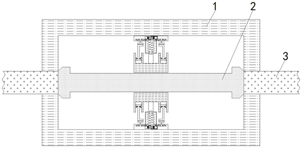
[0004] In order to solve the above-mentioned problem that the internal melt may deform and then change the fusing current when the fuse is working, which affects the use of the voltage transformer, the above-mentioned problem of the deformation of the melt is monitored when the fuse is working to avoid damage caused by the fuse. Body deformation affects the purpose of the use of voltage transformers, and the present invention is realized through the following technical solutions: a high-voltage current detection equipment abnormality monitoring mechanism, including a casing, the two sides of the casing are fixedly connected with power lines, and the interior of the casing is set There is a melt, the inside of the shell and on both sides of the melt include a monitoring mechanism, and the inside of the monitoring mechanism includes a power-saving mechanism

Method used


Image

  • Abnormal monitoring mechanism for high-voltage current detection equipment
  • Abnormal monitoring mechanism for high-voltage current detection equipment
  • Abnormal monitoring mechanism for high-voltage current detection equipment

Examples


Embodiment

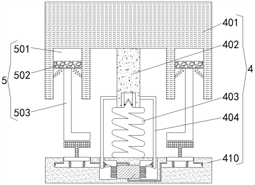
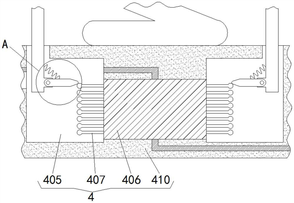
[0024] see Figure 1-6 , a high-voltage current detection equipment abnormality monitoring mechanism 4, including a casing 1, power lines 3 are fixedly connected to both sides of the casing 1, a melt 2 is arranged inside the casing 1, and the inside of the casing 1 is located on both sides of the melt 2 Including a monitoring mechanism 4, the monitoring mechanism 4 includes an insulating block 401 located on the side of the melt 2, the side of the insulating block 401 away from the melt 2 is fixedly connected with a linkage rod 402, and the other side of the linkage rod 402 is fixedly connected There is an air spring 403, and the top of the air spring 403 is provided with an air outlet pipe, and a one-way restrictive valve with the valve opening facing outward is installed inside the air spring 403. When the air spring 403 is squeezed and contracted, the internal gas will gradually be discharged through the air outlet pipe. To prevent the normal deformation of the melt 2 from ...


PUM


Abstract

The invention provides a high-voltage current detection equipment abnormity monitoring mechanism which comprises a shell, power transmission lines are fixedly connected to the two sides of the shell, a melt is arranged in the shell, monitoring mechanisms are arranged in the shell and located on the two sides of the melt, and power saving mechanisms are arranged in the monitoring mechanisms. According to the abnormity monitoring mechanism for the high-voltage current detection equipment, when a fuse is used, current enters the interior of the shell through the power transmission line and passes through the melt, the temperature of the melt is increased along with the current, when the current is close to fusing current, the temperature of the melt is high, and the melt is softened, and at the moment, the monitoring mechanism monitors the deformation degree of the melt; and when the use of the voltage transformer is influenced by the deformation of the melt, a worker is reminded to replace the fuse, so that the purposes of monitoring the deformation degree of the melt and preventing the use of the voltage transformer from being influenced by the deformation of the melt when the fuse works are achieved.

Description

technical field [0001] The invention relates to the technical field of voltage transformers, in particular to an abnormal monitoring mechanism for high-voltage current detection equipment. Background technique [0002] Similar to a transformer, a voltage transformer is an instrument used to transform the voltage on the line, mainly to measure the voltage, current, power and electric energy of the line, or to protect valuable equipment, motors and transformers in the line when the line fails. In order to prevent the voltage transformer from being damaged by high voltage, a high voltage fuse needs to be installed inside. [0003] When the high-voltage fuse is used, its internal melt will fuse when the current reaches a certain level, which will cause the circuit to break. However, when the current is close to the fuse size, the melt will soften. When the vibration force of the device is applied, the melt will gradually deform, resulting in a decrease in the diameter of the me...

Claims


Application Information

Patent Timeline
Patent Type & Authority Applications(China)
IPC IPC(8): H01F27/40H01F38/26H01H85/05H01H85/30
Inventor 韦莫密
Owner 广西通量能源技术有限公司
Learn More