
Winding head for steel wire ring cloth wrapping machine and steel wire ring cloth wrapping machine

A bead ring and wrapping technology, which is applied in the field of auxiliary equipment for tire production, can solve the problems of detachment of the material head, affecting the wrapping efficiency of a traveler wrapping machine, etc., and achieves the effect of improving wrapping efficiency.

Active Publication Date: 2022-04-15
LINK-ASIA SMART TECH (SUZHOU) CO LTD
View PDF10 Cites 1 Cited by
  • Summary
  • Abstract
  • Description
  • Claims
  • Application Information

AI Technical Summary

Problems solved by technology

Therefore, when the material head clamping structure in the No. 202110664239.9 invention application rotates after clamping the material head of the cloth wrapping strip, there is a situation where the material head breaks away from the material head clamping structure, which affects the cloth wrapping efficiency of the wire ring cloth wrapping machine

Method used


Image

  • Winding head for steel wire ring cloth wrapping machine and steel wire ring cloth wrapping machine
  • Winding head for steel wire ring cloth wrapping machine and steel wire ring cloth wrapping machine
  • Winding head for steel wire ring cloth wrapping machine and steel wire ring cloth wrapping machine

Examples


Embodiment Construction

[0022] The following will clearly and completely describe the technical solutions in the embodiments of the present invention with reference to the accompanying drawings in the embodiments of the present invention. Obviously, the described embodiments are only some of the embodiments of the present invention, not all of them. Based on the embodiments of the present invention, all other embodiments obtained by persons of ordinary skill in the art without making creative efforts belong to the protection scope of the present invention.

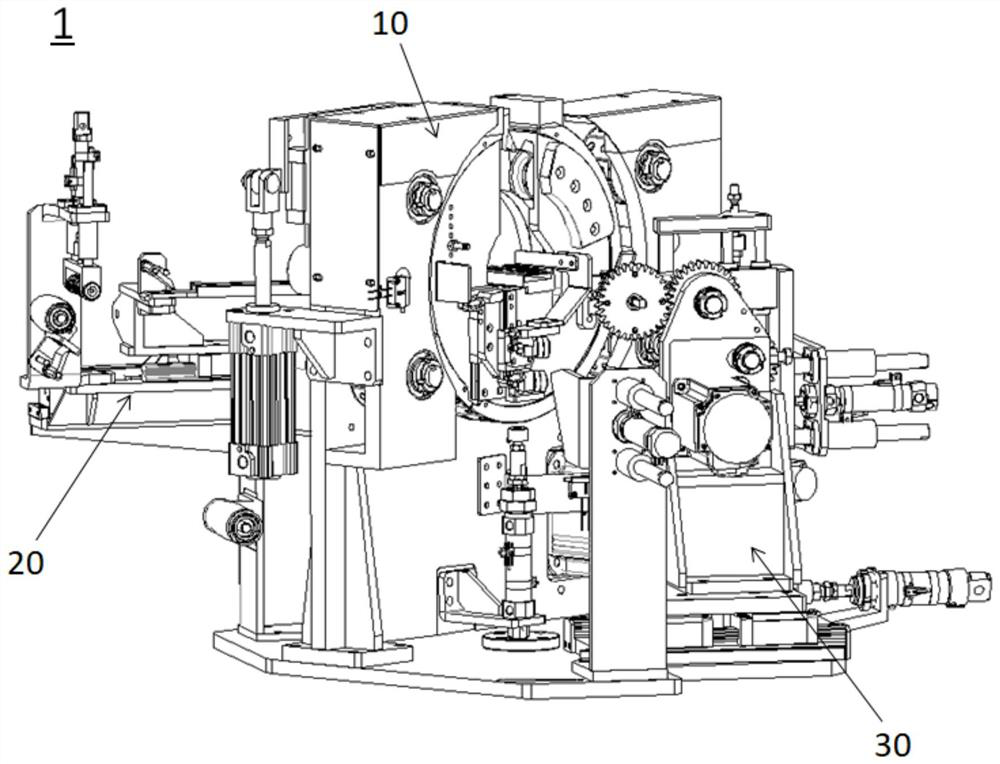
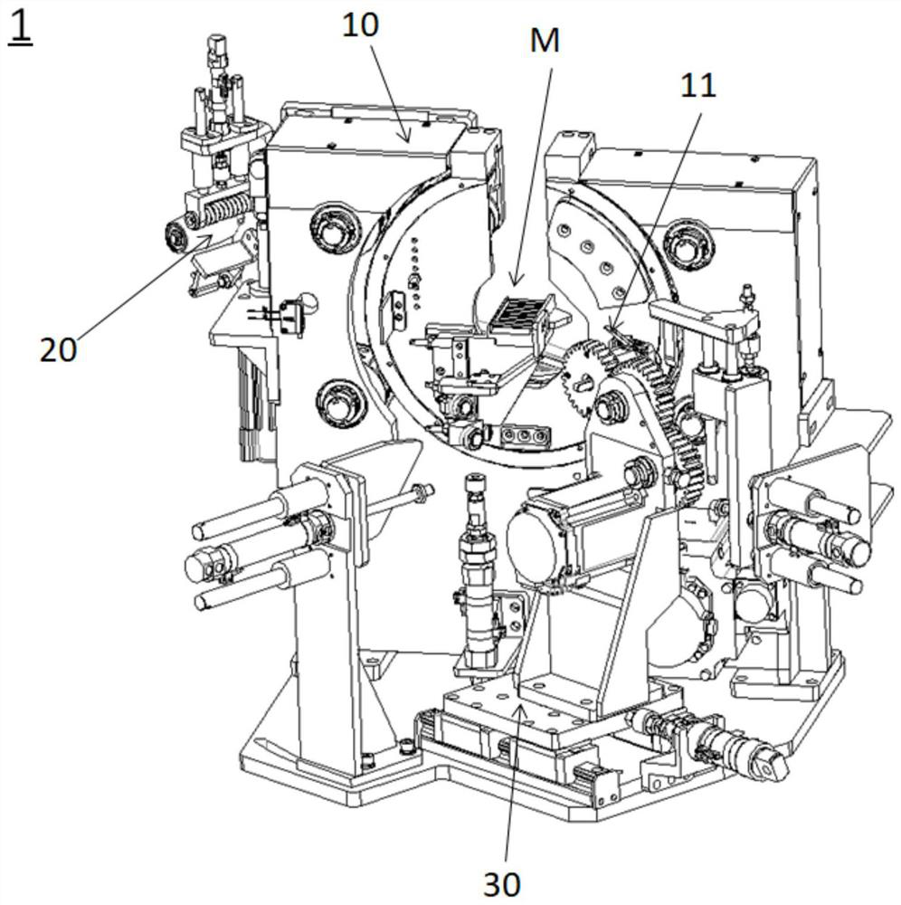
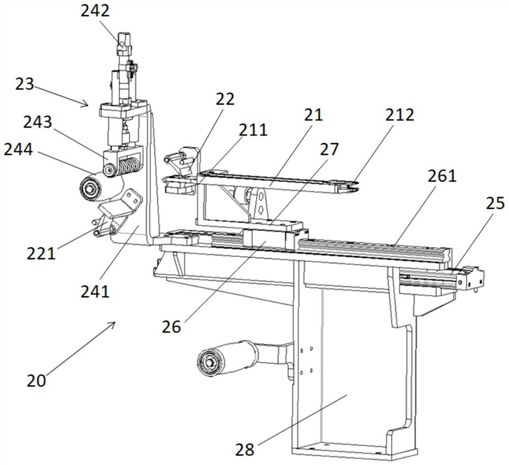
[0023] as attached Figures 1 to 6 As shown, the present invention discloses a winding head 1 for a wire loop wrapping machine, which includes: a winding ring device 10 provided with a storage roller 11, a feeding device 20 and a storage driving device 30; The feeding device 20 is used to transport the wrapping strip 100 to the storage roller 11; the storage driving device 30 is used to drive the rotation of the storage roller 11 to wind the wrap...


PUM

PropertyMeasurementUnit
lengthaaaaaaaaaa

Abstract

The invention discloses a winding head for a steel wire ring cloth wrapping machine. The winding head comprises a winding ring device provided with a material storage roller, a material conveying device and a material storage driving device. The material conveying device is used for conveying a cloth wrapping strip belt to the material storage roller; the material storage driving device is used for driving the material storage roller to rotate so as to wind the cloth wrapping strip with the preset length onto the material storage roller for temporary storage; the winding ring device is used for winding the wrapping cloth strip temporarily stored on the storage roller onto a steel wire ring; wherein the material conveying device comprises a material conveying plate, a first retaining element and a cloth wrapping strip temporary storage device, the cloth wrapping strip temporary storage device is arranged on the upstream of one side of a feeding port of the material conveying plate, and the first retaining element is arranged between the cloth wrapping strip temporary storage device and the feeding port of the material conveying plate. The problem that the stub bar of the cloth wrapping strip is easily separated from a stub bar clamping structure when rotating after being clamped is mainly solved by arranging the first retaining element and the cloth wrapping strip temporary storage device, and then the cloth wrapping efficiency of the steel wire ring cloth wrapping machine is improved.

Description

technical field [0001] The invention relates to the field of tire production auxiliary equipment, in particular to a winding head with a wrapping strip buffer device and a wire loop wrapping machine provided with the wrapping head. Background technique [0002] An invention patent application of the applicant was published on August 31, 2021. The application number is 202110664239.9, and the name is "A storage roller with a material head clamping structure and a winding head device and its winding method". The material in this invention When the head clamping structure rotates after clamping the material head of the wrapping strip, there is a situation that the material head breaks away from the material head clamping structure, resulting in the cloth wrapping strip being unable to be temporarily stored on the storage roller. Specifically, when the head of the wrapping strip is pressed by the head clamping structure, the storage roller rotates to wind the predetermined lengt...

Claims


Application Information

Patent Timeline
Patent Type & Authority Applications(China)
IPC IPC(8): B29D30/50
Inventor 许平峰赵璞夏银涛
Owner LINK-ASIA SMART TECH (SUZHOU) CO LTD
Learn More