Optical transport network service fault positioning method and device

An optical transmission network and service fault technology, applied in the field of data communication, can solve the problems of imperfect passive notification of equipment, unsuitable for ordinary users, and inability to perform effective positioning, and achieve the effect of reducing the difficulty of fault location.

Pending Publication Date: 2022-04-19
BEIJING GW TECH +2
View PDF0 Cites 0 Cited by
  • Summary
  • Abstract
  • Description
  • Claims
  • Application Information

AI Technical Summary

Problems solved by technology

[0003] 1. Active mode. The device locates the fault location through active query. This method requires the staff to have professional technical support capabilities and certain knowledge storage. Query the current alarm information, OPUk alarm, and OPUk payload type through the SNMP protocol Coding (PT) value, bandwidth traffic, OPUk multiplexing structure indicator (MSI) overhead and other information are then comprehensively analyzed to determine the fault location, which is not suitable for ordinary users
[0004] 2. Passive method. The passive notification of equipment is not perfect. At present, only alarms can be reported to the network management system through passive notification, but the PT value of OPUk, the MSI overhead of OPUk, bandwidth traffic and other information do not belong to the scope of alarm notification and will not be used as a Therefore, it is impossible to effectively locate

Method used


Image

  • Optical transport network service fault positioning method and device
  • Optical transport network service fault positioning method and device
  • Optical transport network service fault positioning method and device

Examples


Embodiment Construction

[0026] The following will clearly and completely describe the technical solutions in the embodiments of the application with reference to the drawings in the embodiments of the application. Apparently, the described embodiments are only some, not all, embodiments of the application. Based on the embodiments in this application, all other embodiments obtained by persons of ordinary skill in the art without making creative efforts belong to the scope of protection of this application.

[0027] The terms "first", "second", "third", "fourth", etc. (if any) in the description and claims of the present invention and the above drawings are used to distinguish similar objects, and not necessarily Used to describe a specific sequence or sequence. It is to be understood that the data so used are interchangeable under appropriate circumstances such that the embodiments of the invention described herein are, for example, capable of practice in sequences other than those illustrated or des...


PUM


Abstract

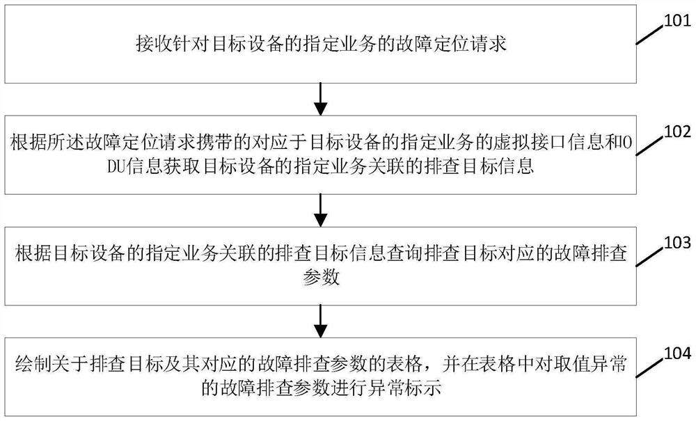
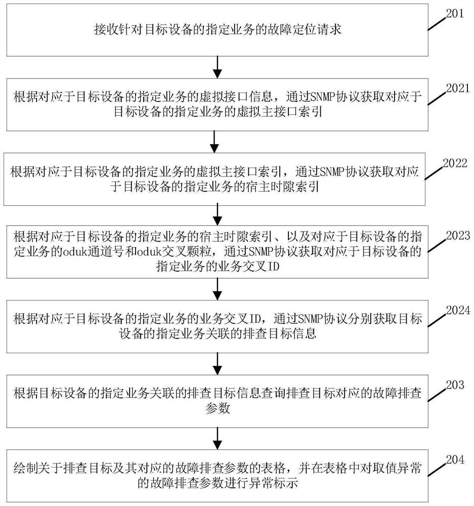
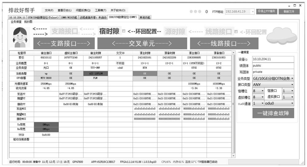
The invention provides an optical transport network service fault positioning method and device. The method comprises the following steps: receiving a fault positioning request for a specified service of target equipment; obtaining troubleshooting target information associated with a specified service of target equipment according to virtual interface information and optical path data unit ODU information corresponding to the specified service of the target equipment carried by the fault positioning request; according to the troubleshooting target information associated with the specified service of the target equipment, querying a fault troubleshooting parameter corresponding to the troubleshooting target; and drawing a table about the troubleshooting targets and the corresponding troubleshooting parameters, and performing exception marking on the troubleshooting parameters with exceptional values in the table. According to the invention, fault positioning can be effectively carried out, and the fault positioning difficulty is greatly reduced.

Description

technical field [0001] The invention relates to the technical field of data communication, in particular to a method and device for locating service faults in an optical transport network. Background technique [0002] Currently, there are two main methods for OTN fault location: [0003] 1. Active mode. The device locates the fault location through active query. This method requires the staff to have professional technical support capabilities and certain knowledge storage. Query the current alarm information, OPUk alarm, and OPUk payload type through the SNMP protocol Code (PT) value, bandwidth traffic, OPUk multiplexing structure indicator (MSI) overhead and other information are then comprehensively analyzed to determine the fault location, which is not suitable for ordinary users. [0004] 2. Passive method. The passive notification of equipment is not perfect. At present, only alarms can be reported to the network management system through passive notification, but th...

Claims


Application Information

Patent Timeline
Patent Type & Authority Applications(China)
IPC IPC(8): H04Q11/00H04B10/079
CPCH04Q11/0062H04Q11/0067H04B10/0791H04B10/0793H04B10/07955H04B10/0795H04Q2011/0083
Inventor 胡楠常秀梅张建鑫
Owner BEIJING GW TECH
Why Eureka
Try Eureka