
Rotating shuttle mechanism and rotating shuttle box

The technology of a rotary hook box and a rotary shuttle is applied to the mechanism of the embroidery machine, the ferrule mechanism of the sewing machine, the embroidery machine, etc. High quality, the effect of ensuring the quality of embroidery

Pending Publication Date: 2022-04-22
ZHEJIANG YUELONG SEWING EQUIP
View PDF7 Cites 0 Cited by
  • Summary
  • Abstract
  • Description
  • Claims
  • Application Information

AI Technical Summary

Problems solved by technology

In the prior art, a fixed structure is usually installed on the outside of the axial end face of the rotary hook to block or stop and fix the inner shuttle so that the inner shuttle does not rotate; however, when the inner shuttle is fixed by the external structure, the outer part and the inner shuttle Maintain a fixed connection, when the outer shuttle rotates to drive the upper thread around the inner shuttle, the connection between the outer part and the inner shuttle will block this, so that the upper thread loop cannot be threaded, resulting in broken upper thread, reducing the quality of sewing and embroidery

Method used


Image

  • Rotating shuttle mechanism and rotating shuttle box
  • Rotating shuttle mechanism and rotating shuttle box
  • Rotating shuttle mechanism and rotating shuttle box

Examples


Embodiment Construction

[0031] In order to make the purpose, technical solutions and advantages of the embodiments of the present invention clearer, the technical solutions in the embodiments of the present invention will be clearly and completely described below in conjunction with the drawings in the embodiments of the present invention. Obviously, the described embodiments It is a part of embodiments of the present invention, but not all embodiments. Based on the embodiments of the present invention, all other embodiments obtained by persons of ordinary skill in the art without making creative efforts belong to the protection scope of the present invention. It should be noted that, in the case of no conflict, the embodiments in the present application and the features in the embodiments can be combined arbitrarily with each other.

[0032] It should be noted that in this article, relational terms such as first and second are only used to distinguish one entity or operation from another entity or o...


PUM


Abstract

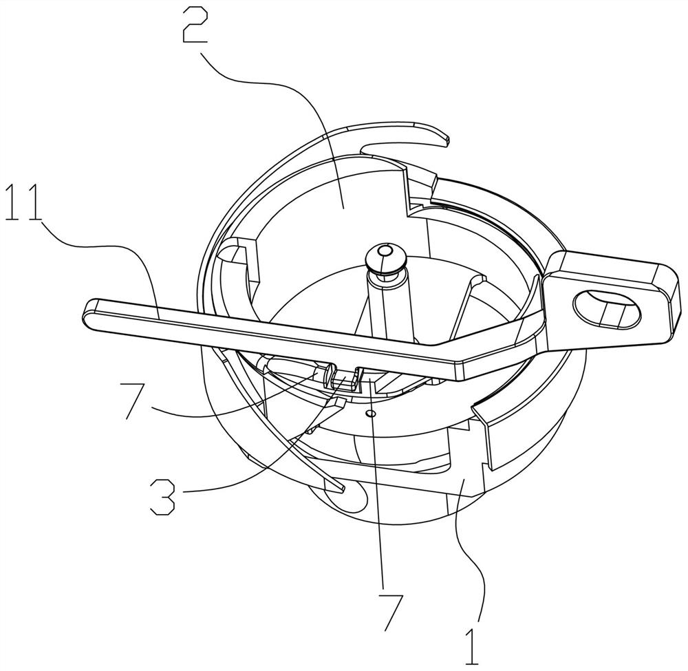
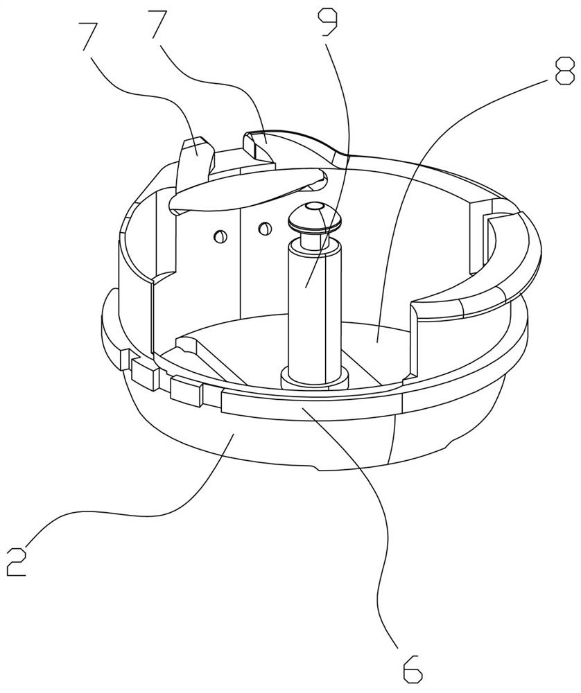
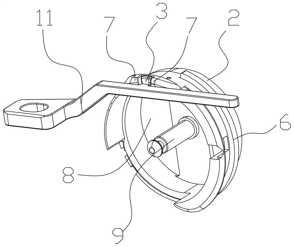
The invention discloses a rotating shuttle mechanism, and relates to the technical field of sewing equipment. Comprising an outer shuttle, an inner shuttle and an inner shuttle limiting piece, an inner shuttle containing cavity is formed in the outer shuttle, a guide groove is further formed in the inner wall of the inner shuttle containing cavity, a guide rail is arranged on the outer surface of the inner shuttle, and the inner shuttle limiting piece is fixed to a main body structure of the rotating shuttle box; the inner shuttle is provided with a stop block for stopping the inner shuttle limiting piece, the inner shuttle limiting piece and the stop block are both arranged to be magnetic pieces, and the side end face of the inner shuttle limiting piece and the end face of the corresponding stop block have the same magnetic pole. The rotating shuttle mechanism disclosed by the invention is convenient for thread release, and the sewing embroidery quality is greatly improved. The invention further discloses a rotating shuttle box which comprises a plurality of rotating shuttle mechanisms, a plurality of rotating shuttle rotating shafts and a driving main shaft. A driven bevel gear is arranged on the rotating shuttle rotating shaft, a plurality of driving bevel gears are arranged on the driving main shaft, and the driving main shaft rotates to drive the outer shuttles to rotate. The rotating shuttle box disclosed by the invention can support high-capacity sewing embroidery work and further meet production requirements.

Description

technical field [0001] The invention relates to the technical field of sewing equipment, in particular to a hook mechanism and a hook box. Background technique [0002] The rotary hook is an important structural part of the sewing machine. The rotary hook includes an outer shuttle and an inner shuttle. The outer shuttle rotates under the external drive, while the inner shuttle is arranged inside the outer shuttle and does not rotate. Enlarging the upper thread loop and driving the upper thread to rotate around the shuttle in the inner shuttle for a circle, the upper thread loop can be looped on another upper thread, thereby achieving embroidery, sewing and other weaving purposes. [0003] During the above-mentioned running process of rotary hook, its inner shuttle needs to keep the state of not rotating all the time, but its outer shuttle will keep continuously rotating, and inner shuttle is arranged in the outer shuttle again. Therefore, how to fix the inner shuttle and n...

Claims


Application Information

Patent Timeline
Patent Type & Authority Applications(China)
IPC IPC(8): D05B57/14D05B57/26D05C11/18
CPCD05B57/14D05B57/26D05C11/18
Inventor 陈天池张汉苗郑邓飞楼凯
Owner ZHEJIANG YUELONG SEWING EQUIP
Learn More