Vehicle lamp system

A technology for vehicles and lamps, applied in the direction of headlights, road vehicles, vehicle parts, etc., can solve problems such as differences in illumination brightness

Pending Publication Date: 2022-04-26
STANLEY ELECTRIC CO LTD
View PDF1 Cites 0 Cited by
  • Summary
  • Abstract
  • Description
  • Claims
  • Application Information

AI Technical Summary

Problems solved by technology

However, in many liquid crystal elements, since there is a viewing direction (best viewing direction) determined by the relationship with the alignment ...

Method used


Image

  • Vehicle lamp system
  • Vehicle lamp system
  • Vehicle lamp system

Examples


Embodiment Construction

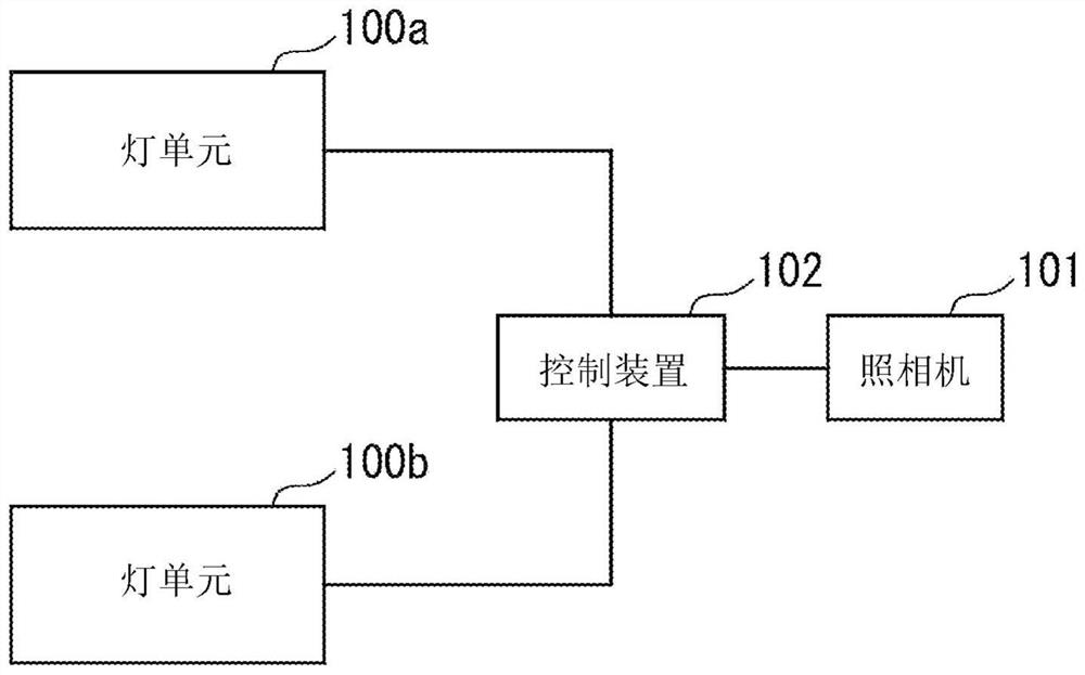
[0029] figure 1 It is a diagram showing the configuration of a vehicle headlamp system according to an embodiment. figure 1 The illustrated vehicle lamp system is configured to include a pair of lamp units (vehicle headlamps) 100 a and 100 b , a camera 101 , and a control device 102 . This vehicular headlight system detects the positions of vehicles in front, pedestrians' faces, etc. existing around the vehicle based on the images captured by the camera 101, and sets a certain range including the positions of the vehicles in front to be non-illuminated. As for the range (light reduction area), the range other than this is set as the light irradiation range and selectively irradiated with light.

[0030] The lamp units 100a and 100b are arranged at predetermined positions on the left and right of the front of the vehicle, and form irradiation light for illuminating the front of the vehicle. In the vehicular lamp system of the present embodiment, the irradiated lights generate...


PUM


Abstract

The purpose of the present invention is to reduce unevenness in brightness of irradiation light generated in a vehicle lamp system using a liquid crystal element. A vehicle lamp system includes: a lamp unit disposed at a front portion of a vehicle; and a control unit that controls the operation of the lamp unit, the lamp unit having: a light source that is controlled by the control unit and emits light; a liquid crystal element which is controlled by the control unit and forms irradiation light using light emitted from the light source; and a lens that projects irradiation light formed by the liquid crystal element toward the periphery of the vehicle, light from the light source is incident on the liquid crystal element at a wide angle, the light incident surface has at least a first region to which more light from a direction along a viewing direction of the liquid crystal element is incident, and a second region to which more light from a direction along the viewing direction of the liquid crystal element is incident. The control unit drives the liquid crystal element by setting the first voltage in the first region to be relatively low and setting the second voltage in the second region to be relatively high.

Description

technical field [0001] The present invention relates to, for example, a system for performing light irradiation in a desired pattern around a vehicle (front, etc.). Background technique [0002] Japanese Unexamined Patent Application Publication No. 2005-183327 (Patent Document 1) discloses a vehicle headlamp including: a light emitting unit composed of at least one LED; part of the light, forming a cut-off of a light distribution pattern suitable for vehicle headlights, the above-mentioned light-shielding unit is composed of an electro-optical element with a dimming function and a control unit that performs dimming control on the electro-optic element, and the control unit controls the light. The electric switch control of the electro-optic element selectively dims the dimming part, thereby changing the shape of the light distribution pattern. As the electro-optical element, for example, a liquid crystal element is used. [0003] However, when the vehicle is illuminated f...

Claims


Application Information

Patent Timeline
IPC IPC(8): F21S41/64F21S41/25F21W102/10F21W107/10F21Y115/10
CPCF21S41/645F21S41/25F21W2102/10F21W2107/10F21Y2115/10G02F1/13F21S41/145F21S41/365F21S41/663F21S41/153B60Q1/14B60Q2300/054B60Q1/1423
Inventor 都甲康夫大和田竜太郎
Owner STANLEY ELECTRIC CO LTD
Why Eureka
Try Eureka