A combined cable tray with fixed structure

A fixed structure and cable tray technology, which is applied in the direction of electrical components, sustainable packaging, packaging recycling, etc., can solve the problems of single width of cable tray, too long overall protective shell, cumbersome maintenance and replacement, etc., so as to avoid the cumbersome installation of bolts , increase the fixed effect, and avoid the effect of economic loss

Active Publication Date: 2022-07-05
徐州浩华电缆桥架有限公司
View PDF7 Cites 1 Cited by
  • Summary
  • Abstract
  • Description
  • Claims
  • Application Information

AI Technical Summary

Problems solved by technology

[0006] In order to solve the above technical problems, the present invention provides a combined cable tray with a fixed structure to solve the problem that most of the existing cable trays are spliced ​​and installed, which is cumbersome to install, and the cable tray only has a single width, which cannot be adjusted , The fixed cable buckles inside the cable bridge are all bolted, and the maintenance and replacement are cumbersome.

Method used


Image

  • A combined cable tray with fixed structure
  • A combined cable tray with fixed structure
  • A combined cable tray with fixed structure

Examples


Embodiment 1

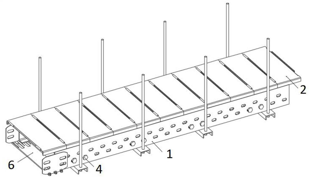
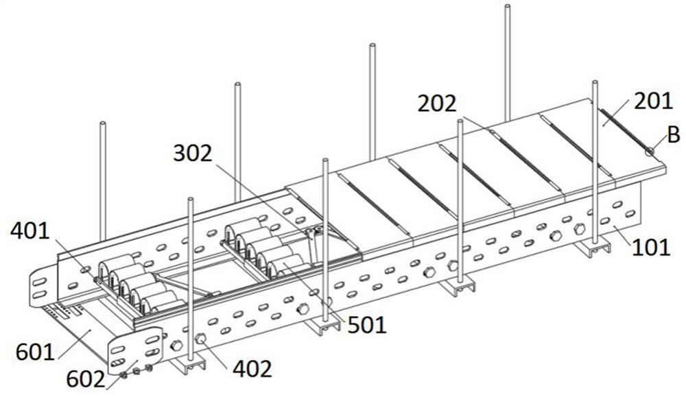
[0030] Example 1: as attached figure 1 to the attached Figure 12Shown: the present invention provides a combined cable tray with a fixed structure, including a groove structure 1; a protective structure 2, the protective structure 2 is a rectangular structure, and the protective structure 2 also includes: a protective plate 201, the protective plate 201 is Rectangular plate structure, the bottom of the front and rear sides of the protective plate 201 are provided with clips facing the lower end; the connecting shaft 202, the connecting shaft 202 is fixed at the left and right ends of the protective plate 201, the left connecting shaft 202 is an extension shaft structure, and the right connecting shaft 202 is a slotted shape, the groove body of the connecting shaft 202 is provided with a slot, and the connection shaft 202 fixed at the left and right positions of the protective plate 201 is used to realize the connection of each group of protective plates 201, and multiple grou...

Embodiment 2

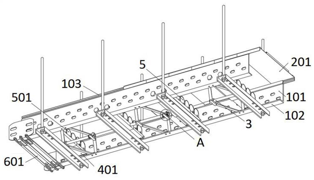
[0033] Embodiment 2: Support structure 4, the support structure 4 adopts a telescopic mechanism, the support structure 4 is clamped and installed at the upper end position of the adjustment structure 3, the support structure 4 is clamped and installed with a fixed structure 5, and the end of the groove structure 1 is connected and installed with a connection Structure 6.

[0034] The support structure 4 further includes: a bearing plate 401, the bearing plate 401 is a rectangular long plate structure, the cross section of the bearing plate 401 is a U-shaped structure, and the bearing plate 401 adopts a telescopic structure; a reinforcing block 403, the reinforcing block 403 is a rectangular block structure , the reinforcement block 403 is fixed at the position of the end of the bearing plate 401, the reinforcement block 403 is in a vertical structure, the reinforcement block 403 is provided with three sets of mounting holes, and the bottom of the reinforcement block 403 is prov...

Embodiment 3

[0038] Embodiment 3: The connecting structure 6 can also be installed at a corner, and an extension plate with a waist hole is added to the outer connecting plate 602, so that the connecting plate 602 and the sliding plate 601 form a corner with an angle of fifteen degrees. board, so that the connecting structure 6 can be combined according to different needs, so that the connecting structure 6 can be adapted to the corners of the cables with different angles.


PUM


Abstract

The invention provides a combined cable tray with a fixed structure, comprising a groove structure; a protection structure, wherein the protection structure is a rectangular structure, and the protection structure further comprises: a protection plate, the protection plate is a rectangular plate structure, the front and rear of the protection plate The side bottoms are all provided with clips facing the lower end; the connecting shaft, the connecting shaft is fixed at the left and right ends of the protective plate, the left connecting shaft is an extension shaft structure, the right connecting shaft is a slot shape, and the groove body of the connecting shaft is opened. There is a slot, the protective structure is clamped and installed on the top of the groove body structure, and the bottom position of the groove body structure is connected and installed with an adjustment structure; the support structure, the support structure adopts a telescopic mechanism, and the support structure is clamped and installed at the upper end of the adjustment structure A fixed structure is installed on the support structure, and a connection structure is installed at the end of the groove structure. When the protective plate installed outdoors is damaged, it can be replaced separately, avoiding excessive economic losses.

Description

technical field [0001] The invention belongs to the technical field of cable installation equipment, and more particularly relates to a combined cable tray with a fixed structure. Background technique [0002] Cable is a device for transmitting high-voltage electricity, which is mostly used in large-scale equipment in factories. Usually, cables are laid and installed using bridges. Cable bridges are composed of brackets, support arms and installation accessories. The bridge frame in the building can be erected independently, or it can be laid on various buildings (structures) and pipe gallery supports. It should reflect the characteristics of simple structure, beautiful appearance, flexible configuration and convenient maintenance. All parts need to be galvanized. , installed in the open air bridge outside the building. [0003] Application No.: CN201910271741.6, the present invention discloses a cable tray equipped with adjustable wiring components, including a rack mounti...

Claims


Application Information

Patent Timeline
Patent Type & Authority Patents(China)
IPC IPC(8): H02G3/04H02G3/06
CPCH02G3/0456H02G3/0406H02G3/0418H02G3/0608Y02W30/80
Inventor 王肖
Owner 徐州浩华电缆桥架有限公司
Why Eureka
Try Eureka