Mining pressure relief boundary detection method

A detection method and boundary technology, applied in the field of mine engineering, can solve problems such as low reliability, loss, complex geological structure, etc., and achieve the effect of improving accuracy and obtaining accurately

Pending Publication Date: 2022-05-06
CHONGQING UNIV +1
View PDF0 Cites 0 Cited by
  • Summary
  • Abstract
  • Description
  • Claims
  • Application Information

AI Technical Summary

Problems solved by technology

[0002] The existing mining pressure relief boundary detection method has low reliability, coupled with the complex geological structure, it is impossible to accurately deduce the real pressure relief boundary, which in turn leads to inaccurate judgment of the location of coal and gas outbursts, which eventually lead to safety accidents and economic losses
At the same time, using a single detection method to detect the mining pressure relief boundary will have a large error

Method used


Image

  • Mining pressure relief boundary detection method
  • Mining pressure relief boundary detection method
  • Mining pressure relief boundary detection method

Examples


Embodiment 1

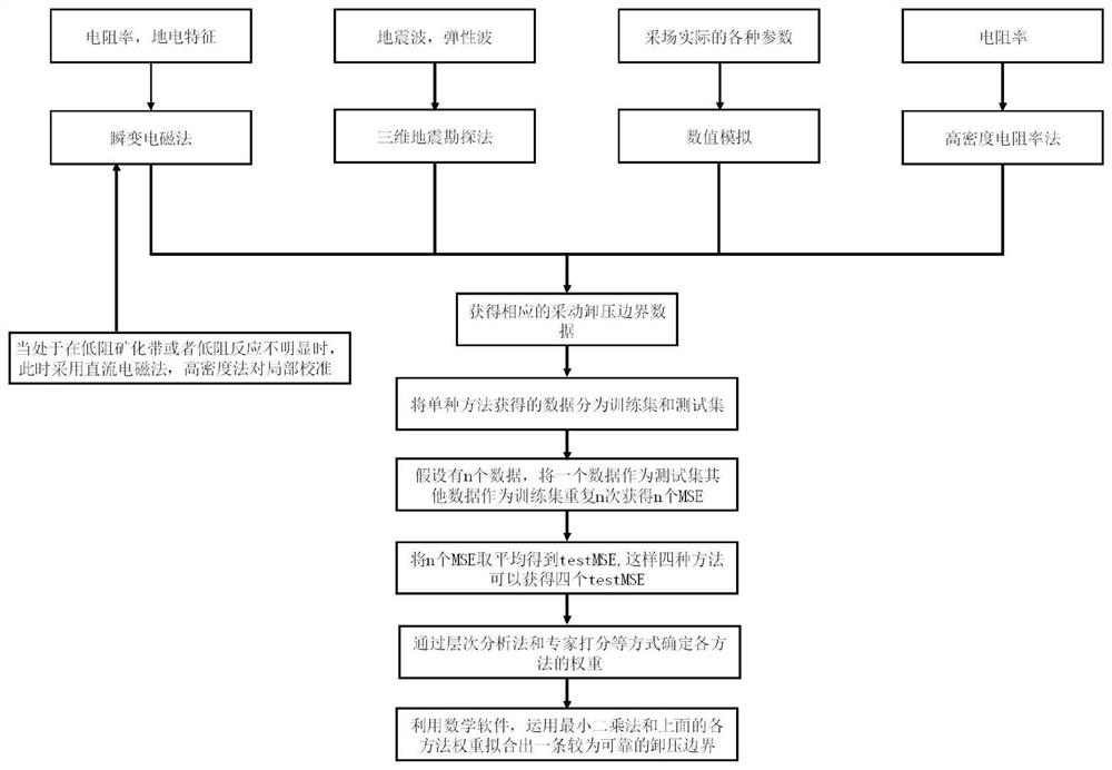
[0032] see figure 1 , this embodiment discloses a mining pressure relief boundary detection method, including the following steps:

[0033] 1) Use multiple methods to obtain multiple groups of mining pressure relief boundary data.

[0034] 1.1) In the mining stable area, multiple sections are observed by using the transient electromagnetic method, and the geoelectric characteristics of each section are obtained, and the electromagnetic-pressure relief boundary is obtained. When there is a low-resistance mineralization zone or the low-resistance response is not obvious, the DC electromagnetic method and the high-density method are used to test the local area to improve the electromagnetic-pressure relief boundary.

[0035] 1.2) Using 3D seismic exploration technology, using p-wave reflection to obtain rock formation properties, and analyzing the profile to determine the acoustic wave-pressure relief boundary.

[0036] 1.3) Numerical simulation is carried out according to the ...

Embodiment 2

[0045] see figure 1 , this embodiment discloses a mining pressure relief boundary detection method, including the following steps:

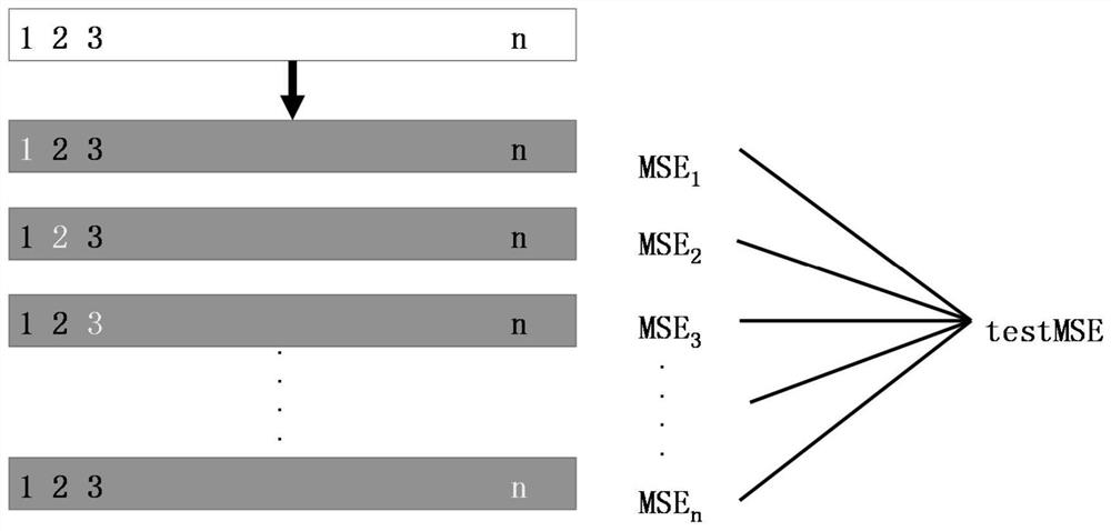
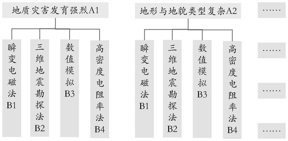
[0046] 1) In the mining stable area, the transient electromagnetic method, seismic exploration, numerical simulation method and high-density electrical method are used to obtain the corresponding mining pressure relief boundary from different parameter angles, and combined with the actual situation of the stope, the obtained In order to improve the accuracy of each method to determine the boundary, optimize the data of the mining pressure relief boundary.

[0047] 1.1) Multiple sections are observed by using the transient electromagnetic method, and the geoelectric characteristics of each section are obtained, so as to obtain a mining pressure relief boundary. The boundary obtained by this method is called the electromagnetic-pressure relief boundary. If there is a low-resistance mineralization zone within the measurement range of the transient ...


PUM


Abstract

The invention provides a mining pressure relief boundary detection method. According to the method, a transient electromagnetic method, a seismic exploration method, a numerical simulation method and a high-density electrical method are utilized in a mining stable area to obtain corresponding mining pressure relief boundaries from different parameter angles, the data of the obtained mining pressure relief boundaries are optimized in combination with the actual condition of a stope, the accuracy of determining the boundaries by all the methods is improved, and the method is suitable for popularization and application. All the mining pressure relief boundaries after data optimization are fitted, and finally the mining pressure relief boundaries are obtained. According to the method, the complexity and variability of the geological structure are considered, the determination accuracy of the mining pressure relief boundary is improved, and the mining pressure relief boundary can be accurately obtained. The method is of great significance in eliminating coal and gas outburst danger, and provides powerful guarantee for safe mining of coal mines.

Description

technical field [0001] The invention relates to the field of mine engineering, in particular to a method for detecting the pressure relief boundary of mining. Background technique [0002] The existing mining pressure relief boundary detection method has low reliability, coupled with the complex geological structure, it is impossible to accurately deduce the real pressure relief boundary, which in turn leads to inaccurate judgment of the location of coal and gas outbursts, and ultimately leads to safety accidents and economic losses. At the same time, there will be large errors in detecting the pressure relief boundary of mining with a single detection method. Therefore, it is of great practical significance to establish a method suitable for mining pressure relief boundary detection. Contents of the invention [0003] The purpose of the present invention is to provide a mining pressure relief boundary detection method to solve the problems in the prior art. [0004] The...

Claims


Application Information

Patent Timeline
Patent Type & Authority Applications(China)
IPC IPC(8): G01V11/00
CPCG01V11/00
Inventor 梁运培田玉娇冉启灿黄旭超郑皓泷王志辉张碧川孔繁杰邹全乐
Owner CHONGQING UNIV
Why Eureka
Try Eureka