
OBC and DC/DC integrated charger, control method and related equipment

A technology that integrates chargers and controllers, applied in current collectors, safety/protection circuits, charging/discharging current/voltage regulation, etc., and can solve problems such as overcurrent faults

Pending Publication Date: 2022-05-06
SHINRY TECH
View PDF0 Cites 0 Cited by
  • Summary
  • Abstract
  • Description
  • Claims
  • Application Information

AI Technical Summary

Problems solved by technology

[0002] In OBC and DC / DC integrated charger applications, the total output of the high-voltage electrical equipment connected to the output of the on-board charger (On-board Charger, OBC) and the DC-DC (Direct current / Direct current, DC / DC) converter The power cannot exceed the total input power of the OBC, and its total output power exceeding the total input power of the OBC will cause the input current of the OBC to exceed the limit of the charging gun, and an overcurrent fault occurs. When the on-board controller and the OBC controller use serial communication to transmit the OBC When the current value of the resonant cavity is high, because there is a delay in data transmission, when the load connected to the output end of the DC / DC converter suddenly increases, the OBC controller cannot adjust the output power of the OBC in time. At this time, the high-voltage electrical equipment connected to the output end of the OBC The sum of the output power of the DC / DC converter and the DC / DC converter will exceed the total input power of the OBC, causing the input current of the OBC to exceed the limit of the charging gun, and an overcurrent fault occurs

Method used


Image

  • OBC and DC/DC integrated charger, control method and related equipment
  • OBC and DC/DC integrated charger, control method and related equipment
  • OBC and DC/DC integrated charger, control method and related equipment

Examples


Embodiment Construction

[0016] In order to enable those skilled in the art to better understand the solution of the present application, the technical solution in the embodiment of the application will be clearly and completely described below in conjunction with the accompanying drawings in the embodiment of the application. Obviously, the described embodiment is only It is a part of the embodiments of this application, not all of them. Based on the embodiments in this application, all other embodiments obtained by persons of ordinary skill in the art without creative efforts fall within the protection scope of this application.

[0017] The terms "first", "second" and the like in the specification and claims of the present application and the above drawings are used to distinguish different objects, rather than to describe a specific order. Furthermore, the terms "include" and "have", as well as any variations thereof, are intended to cover a non-exclusive inclusion. For example, a process, method...


PUM


Abstract

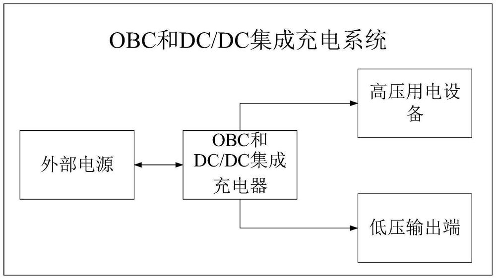
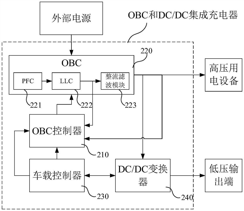
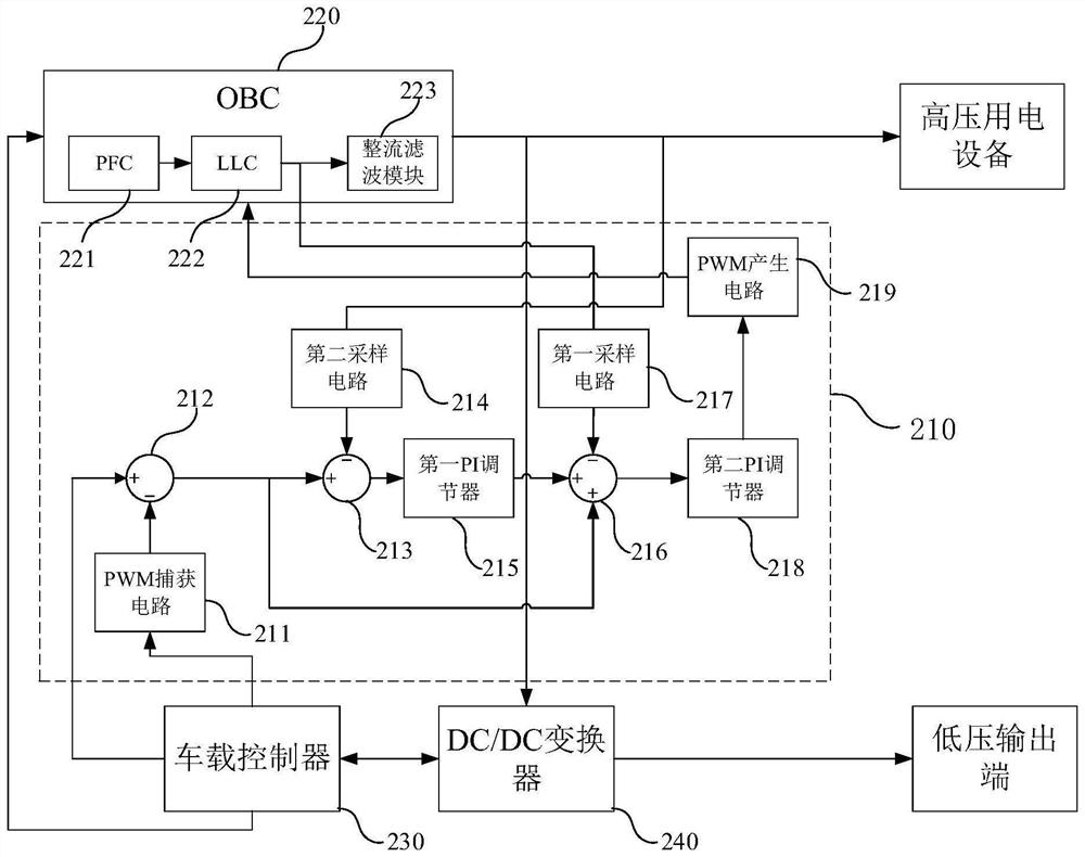
The embodiment of the invention provides an OBC and DC / DC integrated charger, a control method and related equipment, the OBC and DC / DC integrated charger comprises an OBC, an OBC controller, a vehicle-mounted controller and a DC / DC converter, a first output end of the DC / DC converter is connected with an input end of the vehicle-mounted controller, a second output end of the DC / DC converter is connected with a low-voltage output end, and the OBC controller is connected with the vehicle-mounted controller. The first output end of the vehicle-mounted controller is connected with the first input end of the OBC controller, the second output end of the vehicle-mounted controller is connected with the second input end of the OBC controller, the third output end of the vehicle-mounted controller is connected with the first input end of the DC / DC converter, and the output end of the OBC controller is connected with the first input end of the OBC controller. According to the invention, the resonant cavity current of the OBC can be adjusted in time when the load of the electric equipment at the DC / DC output end is suddenly increased, so that the input current of the OBC is prevented from exceeding the limitation of the charging gun, and an overcurrent fault is avoided.

Description

technical field [0001] The application belongs to the field of on-board chargers, and specifically relates to an OBC and DC / DC integrated charger, a control method and related equipment. Background technique [0002] In OBC and DC / DC integrated charger applications, the total output of the high-voltage electrical equipment connected to the output of the on-board charger (On-board Charger, OBC) and the DC-DC (Direct current / Direct current, DC / DC) converter The power cannot exceed the total input power of the OBC, and its total output power exceeding the total input power of the OBC will cause the input current of the OBC to exceed the limit of the charging gun, and an overcurrent fault occurs. When the on-board controller and the OBC controller use serial communication to transmit the OBC When the current value of the resonant cavity is high, because there is a delay in data transmission, when the load connected to the output end of the DC / DC converter suddenly increases, the...

Claims


Application Information

Patent Timeline
Patent Type & Authority Applications(China)
IPC IPC(8): H02J7/00
CPCH02J7/007H02J7/00304
Inventor 祁嘉荣邓家勇刘鹏飞吴壬华
Owner SHINRY TECH
Learn More