Method and device for multi-station near-net forming of spatial curved surface

A near-net-shape, multi-station technology, used in manufacturing tools, metal processing equipment, welding equipment, etc., can solve the problem of increasing the time and process of repeated positioning, inability to add and subtract materials at the same time, and low flexibility in subtractive processing, etc. problems, to ensure air tightness, expand the scope of work, and shorten the working time.

Inactive Publication Date: 2022-05-10
江西应用科技学院
View PDF0 Cites 0 Cited by
  • Summary
  • Abstract
  • Description
  • Claims
  • Application Information

AI Technical Summary

Problems solved by technology

For some complex parts, further grinding is required after material addition/subtraction processing, but the function of material reduction is not complete, so the flexibility of material reduction processing is low under special working conditions
Especially when the parts are irr

Method used


Image

  • Method and device for multi-station near-net forming of spatial curved surface
  • Method and device for multi-station near-net forming of spatial curved surface
  • Method and device for multi-station near-net forming of spatial curved surface

Examples


Embodiment 1

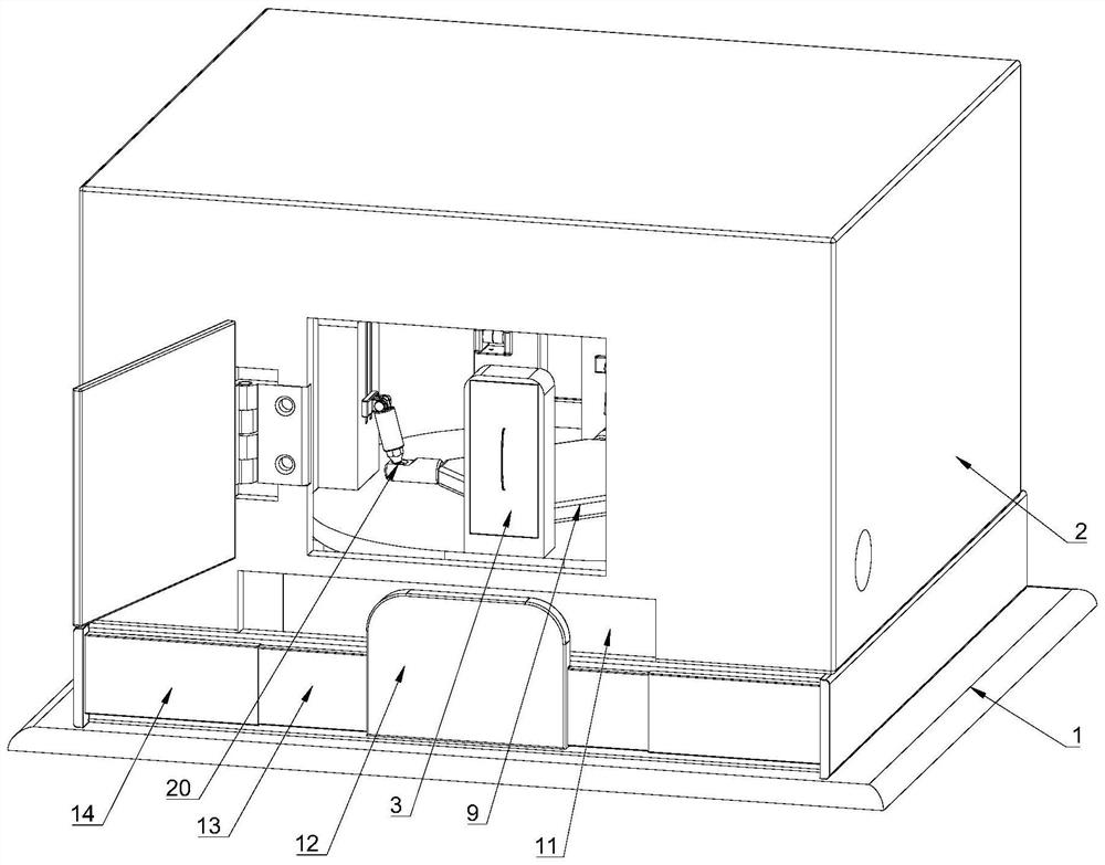
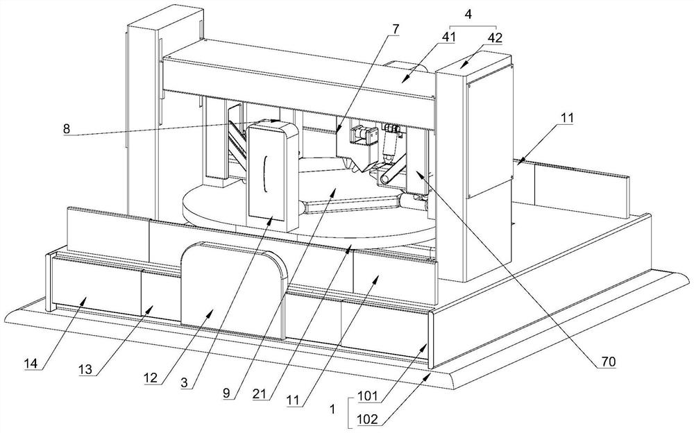
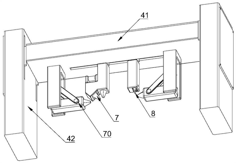
[0077] Such as Figures 1 to 26 As shown, a device for a multi-station near-net shape space curved surface of the present invention includes a fixed base 1, a first column 3, a gantry crane 4, a material adding module 7, a composite mobile platform, a grinding and cutting material module 8, a laser material reducing Module 70, workbench 9, first connector 20; gantry crane 4 includes gantry crane beam 41 and gantry crane column 42, gantry crane column 42 is located at both ends of gantry crane beam 41 and fixed on the fixed base 1; gantry crane beam 41 is provided with a first drive The mechanism 18, the material addition module 7 and the grinding and cutting module 8 move horizontally relative to the gantry crane beam 41 under the drive of the first drive mechanism 18, and the material addition module 7, the laser material reduction module 70 and the grinding and cutting module 8 are arranged on the gantry crane beam Below 41, the additive module 7 and the grinding and cutting...

Embodiment 2

[0128] Such as Figures 27 to 29 As shown, the device of this embodiment is roughly the same as that of Embodiment 1, the difference is that:

[0129] The number of gantry crane crossbeams 41 in this embodiment is two, and the material-adding module 7 and the material-reducing module 8 are respectively driven by two independent first drive mechanisms 18 (the first drive mechanism 18 is not provided with a coupling 185), and the gantry crane The column 42 is provided with two fourth driving mechanisms 17 for respectively driving the gantry crane beam 41 to move up and down, and the two laser material reduction modules 70 are respectively arranged at the ends of different gantry crane beams 41 .


PUM


Abstract

The invention discloses a device for multi-station near-net forming of a spatial curved surface. The device comprises a fixed base, a first stand column, a material adding module, a composite moving platform, a grinding and cutting material module, a workbench and a laser material reducing module. The material adding module and the grinding and cutting module horizontally move relative to a cross beam of the gantry crane; a lower moving table of the composite moving platform is connected to the lower portion of an upper moving table and can horizontally move relative to the lower moving table, and the upper moving table can horizontally move relative to a fixed base. The gantry crane beam can move up and down relative to the gantry crane stand columns. The at least two first stand columns are arranged on the outer sides of the two ends of the workbench respectively and fixed above the upper moving table, and the workbench can incline relative to the first stand columns. The invention has the advantages of compact structure and the like.

Description

technical field [0001] The invention relates to the field of desktop laser processing equipment, in particular to a method and device for a multi-station near-net-shaping space curved surface. Background technique [0002] In traditional laser processing equipment, the additive processing is performed first, and then the subtractive processing is performed. The additive and subtractive processing cannot be completed at the same time, and the loading and unloading operations and repositioning are required. Although there are currently some additive and subtractive composite equipment, each There are interference problems between stations, which leads to certain limitations in adding and subtracting composite equipment. [0003] With the rapid development of my country's manufacturing industry, the demand for customization of new mechanical equipment is increasing day by day, and the structural integration and complexity of various parts and components are constantly increasin...

Claims


Application Information

Patent Timeline
IPC IPC(8): B23K26/00B23K26/08B23K26/21B23K26/36B23K26/70
CPCB23K26/0093B23K26/0869B23K26/702B23K26/21B23K26/36
Inventor 肖罡仪传明杨钦文李时春戴璐祎詹海鸿
Owner 江西应用科技学院
Why Eureka
Try Eureka