Eureka AIR delivers breakthrough ideas for toughest innovation challenges, trusted by R&D personnel around the world.

Roller body mounting structure on steel belt processing line

A technology of installation structure and processing line, which is applied in metal processing equipment, manufacturing tools, metal rolling, etc., can solve the problem of low roll changing efficiency, and achieve the effect of improving efficiency and quickly changing rolls

Pending Publication Date: 2022-05-13
ZHAOQING HONGWANG METAL IND
View PDF0 Cites 0 Cited by
  • Summary
  • Abstract
  • Description
  • Claims
  • Application Information

AI Technical Summary

Problems solved by technology

[0002] On the steel strip processing line, the transmission, rolling or leveling of the steel strip is generally carried out by clamping the steel strip through the cooperation of the upper and lower roller bodies. After the roller body has been in operation for a period of time, it needs regular maintenance or replacement of the roller body. At present, the upper , The replacement of the lower roller body is done by pulling out the upper and lower rollers sequentially, and the efficiency of changing rollers is low

Method used


Image

  • Roller body mounting structure on steel belt processing line

Examples


Embodiment Construction

[0014] The following specific embodiments of the present invention in conjunction with the accompanying drawings are further described in detail. It should be understood that the specific embodiments described herein are used only to illustrate and explain the present invention and are not intended to limit the present invention.

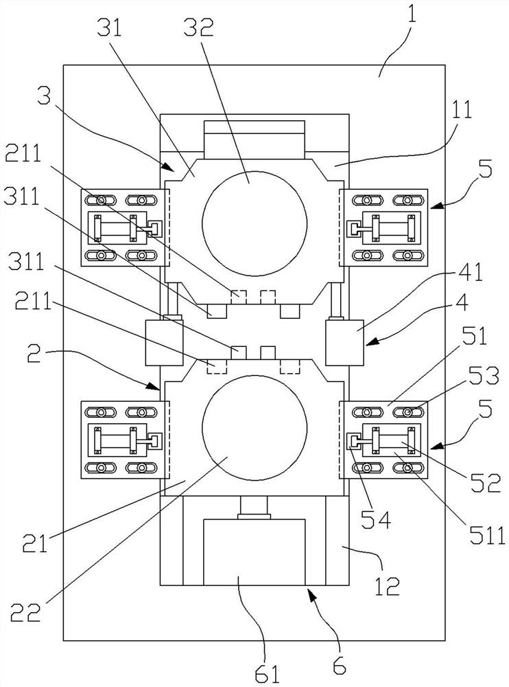
[0015] See Figure 1 , a roll body mounting structure on the steel belt processing line, comprising two support arms 1, the lower roller assembly 2, the upper roller assembly 3 and the first lifting mechanism 4, the two support arms 1 are relatively disposed on both sides of the steel belt conveying direction, each support arm 1 along the vertical direction of the opening of the tolerance groove 11, the capacitive groove 11 in the axis direction of the roller body through the support arm 11, correspondingly support arm 1 above the capacitive groove 11 to form a top wall, the capacity groove 11 below the formation of the bottom wall, the capacity groo...


PUM


Abstract

The roller body mounting structure comprises supporting arms, a lower roller assembly, an upper roller assembly and a first lifting mechanism, the two supporting arms are oppositely arranged on the two sides of the steel belt conveying direction, each supporting arm is provided with a containing groove, and the lower roller assembly comprises a lower roller base installed at the inner bottom end of the containing groove in a liftable mode; the upper roller assembly comprises an upper roller base installed at the top end in the containing groove in a lifting and sliding mode, a plurality of grooves are formed in the top face of the lower roller base or the bottom face of the upper roller base, protrusions matched with the grooves are correspondingly arranged on the bottom face of the upper roller base or the top face of the lower roller base, and the first lifting mechanism is used for driving the upper roller base to ascend and descend. And the top surface of the upper roller seat is matched on the top wall of the accommodating groove or the bottom surface of the upper roller seat is matched with the top surface of the lower roller seat through the bulges and the grooves, so that the upper roller seat and the lower roller seat are pulled out together in the axial direction through external force during roller replacement. The upper roller seat and the lower roller seat can be conveniently pulled out together, roller replacement is achieved, and the roller replacement efficiency is improved.

Description

Technical field [0001] The present invention relates to the field of steel belt processing equipment, specifically to a roll body mounting structure on a steel belt processing line. Background [0002] In the steel belt processing line, the transmission, pressing or flattening of the steel belt is generally through the upper and lower two roller bodies with clamping the steel belt, the roll body in the operation of a period of time, the need for regular maintenance or replacement of the roller body, at present, the replacement of the upper and lower roller body is through the upper and lower rollers in turn to replace, the roller replacement efficiency is low. Contents of the Invention [0003] To solve the above problems, the present invention provides a roll body mounting structure on a steel strip processing line that may improve the efficiency of roller change. [0004] The technical embodiment of the present invention is as follows: a roll body mounting structure on the st...

Claims


Application Information

Patent Timeline
Patent Type & Authority Applications(China)
IPC IPC(8): B21B1/22B21B31/12
CPCB21B1/22B21B31/12
Inventor 刘慧丹陈元王洪君袁尧刘宗昆
Owner ZHAOQING HONGWANG METAL IND
Why Eureka
Eureka Blog
Learn More