Wire folding pliers

A technology of folding wire pliers and bending pliers, applied in the field of folding wire pliers, can solve problems such as laborious operation of electricians, potential safety hazards of electricity use, inconvenient operation, etc., and achieve the effect of getting rid of manual operation, uniform shape, and convenient use of shape

Pending Publication Date: 2022-05-13
张炜秋
View PDF0 Cites 0 Cited by
  • Summary
  • Abstract
  • Description
  • Claims
  • Application Information

AI Technical Summary

Problems solved by technology

[0002] With the popularization of household appliances and the increase of industrial products, there will be a large number of air switches, contactors and relays. During installation and maintenance, it is often encountered that the wire connectors are pressed into the pressure screws of various switches. Usually electricians When crimping, you will choose to directly peel off the insulation of the wire connector, put the wire connector directly under the crimping screw of various electrical switches, and directly twist the screw to press the wire connector or manually use the connector that has been stripped of the insulation After the pliers are bent, they are clamped or bent into a U-shape and placed under the electrical switch screws to press down. This method usually makes the electrician's operation more difficult. It is difficult to ensure the shape of the wire connector and the operation is inconvenient. Small contact area or weak pressure wire lead to electrical safety hazards

Method used


Image

  • Wire folding pliers
  • Wire folding pliers
  • Wire folding pliers

Examples


Embodiment Construction

[0021] The technical solution of the present invention will be described in detail below in conjunction with the accompanying drawings.

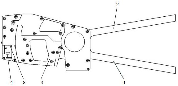
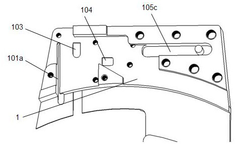
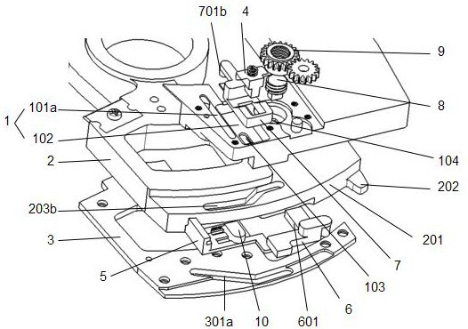
[0022] as attached figure 1 to attach Figure 5 As shown, it includes a first body 1 and a second body 2, the first body 1 and the second body 2 are rotatably connected, one end of the first body 1 is provided with sliding grooves 101a, 105c, and the sliding grooves 101a, 105c The folding line mechanism 5, 10 and the profiling slider 6 are respectively arranged inside, and the profiling slider 6 is arranged perpendicular to the folding line mechanism 5, 10, and the working surface of the first body 1 on one side of the folding line mechanism 5, 10 is provided with Through hole 103, the opposite side of the working surface of the first body 1 is provided with a sliding groove 102b corresponding to the through hole, and the sliding groove 102b is provided with a telescopic sliding mechanism 4, 7, and the folding line mechanism 5, 10 on the fi...


PUM


Abstract

The invention discloses a line folding clamp which comprises a first body and a second body, the first body and the second body are rotationally connected, a sliding groove is formed in one end of the first body, a line folding mechanism and a profiling sliding block are arranged in the sliding groove, and the profiling sliding block is perpendicular to the line folding mechanism. A through hole is formed in the working face of the first body on one side of the line folding mechanism, a sliding groove corresponding to the through hole is formed in the reverse side of the working face of the first body, a telescopic sliding mechanism is arranged in the sliding groove, positioning pin holes are formed in one side of the line folding mechanism and one side of the profiling sliding block on the first body, and positioning mechanisms are arranged in the positioning pin holes. One end of the second body is in an arc shape, a protruding pressing block is arranged at one end of the arc shape, a sliding groove is formed in one face of the second body, a pressing cover with a sliding groove is fixedly installed on the other face of the second body and corresponds to the second body, manual bending of a wire connector is avoided in the wire folding process, and meanwhile it can be guaranteed that the bent shape is uniform.

Description

technical field [0001] The invention relates to a wire folding pliers, which belongs to the technical field of electrical tools. Background technique [0002] With the popularization of household appliances and the increase of industrial products, there will be a large number of air switches, contactors and relays. During installation and maintenance, it is often encountered that the wire connectors are pressed into the pressure screws of various switches. Usually electricians When crimping, you will choose to directly peel off the insulation of the wire connector, put the wire connector directly under the crimping screw of various electrical switches, and directly twist the screw to press the wire connector or manually use the connector that has been stripped of the insulation After the pliers are bent, they are clamped or bent into a U-shape and placed under the electrical switch screws to press down. This method usually makes the electrician's operation more difficult. It...

Claims


Application Information

Patent Timeline
Patent Type & Authority Applications(China)
IPC IPC(8): B21F1/00B21F15/04
CPCB21F1/002B21F15/04
Inventor 张炜秋
Owner 张炜秋
Why Eureka
Try Eureka