Highway bridge pipeline supporting equipment

A technology for pipeline support and highway bridges. It is applied to pipeline supports, mechanical equipment, pipes/pipe joints/fittings, etc. It can solve the problems of inconvenient pipeline fixing, inconvenient adjustment of support height, complicated operation, etc., and achieve fast pipeline fixing and simple structure. , the effect of convenient operation

Inactive Publication Date: 2022-05-13
洪新民
View PDF0 Cites 1 Cited by
  • Summary
  • Abstract
  • Description
  • Claims
  • Application Information

AI Technical Summary

Problems solved by technology

[0004] The purpose of the present invention is to solve the shortcomings of the existing highway bridges, which are inconvenient to fix the pipeline when erecting the pipeline, and at the same time, the supporting height is not easy to adjust, and the shortcomings are complicated to operate, and a kind of highway bridge pipeline support equipment is proposed.

Method used


Image

  • Highway bridge pipeline supporting equipment
  • Highway bridge pipeline supporting equipment
  • Highway bridge pipeline supporting equipment

Examples


Embodiment 1

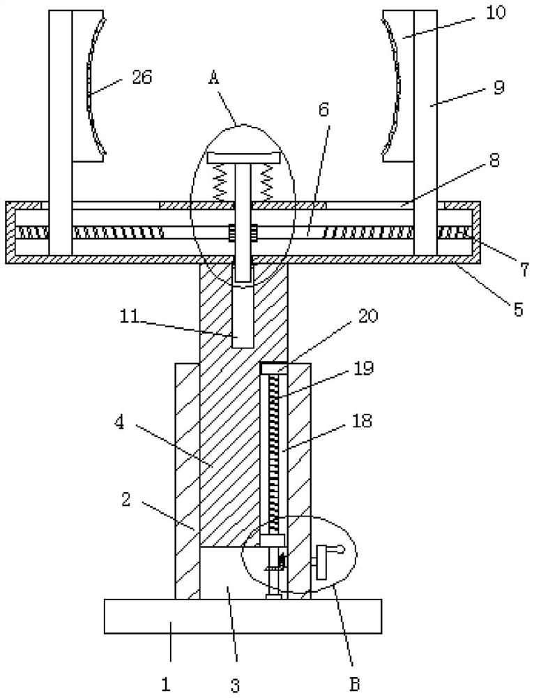
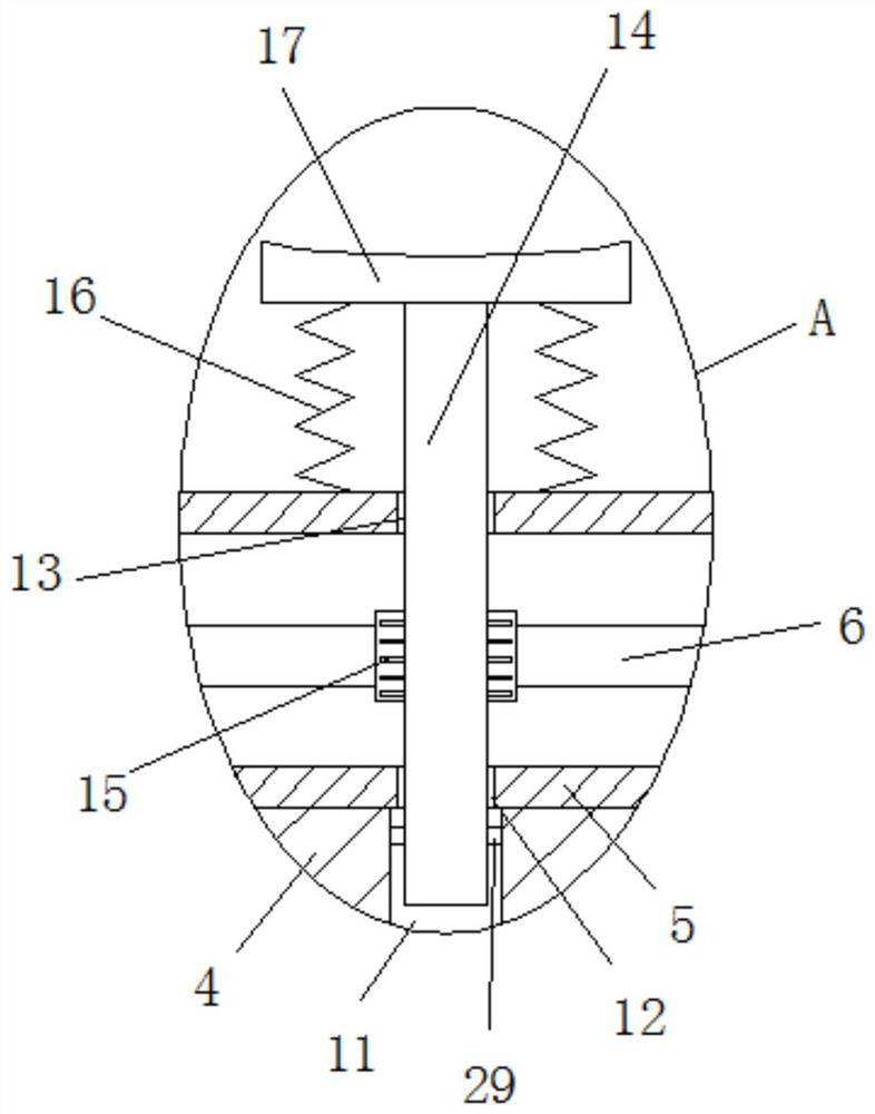
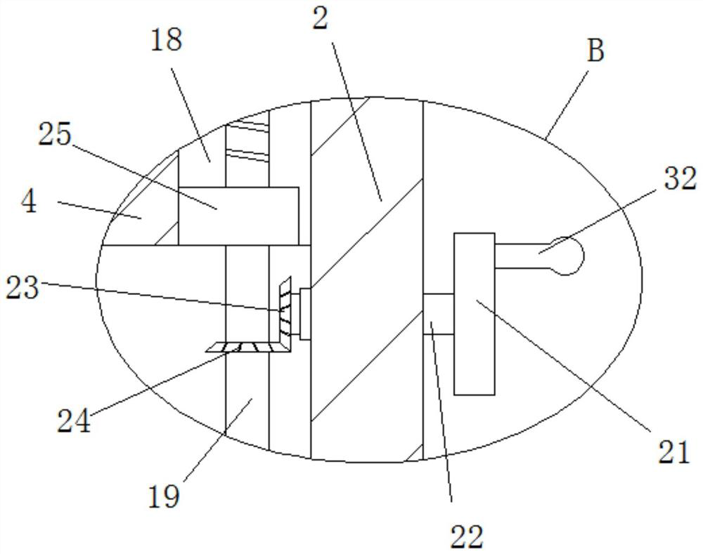
[0027] refer to Figure 1-5 , a highway bridge pipe support device, comprising a base 1, a rectangular column 2 is installed on the top of the base 1, a rectangular hole 3 is opened on the rectangular column 2, a rectangular rod 4 is slidingly installed in the rectangular hole 3, and the top of the rectangular rod 4 is installed There is a support box 5, and the top of the support box 5 is provided with two strip holes 8, and a fixed rod 9 is slidably installed in the two strip holes 8, and a fixing mechanism is installed on the inside of the two fixed rods 9, and the support box 5 A threaded mechanism is installed inside, and the two fixed rods 9 are connected with the threaded mechanism. A conflicting mechanism is installed on the support box 5, and the conflicting mechanism is connected with the threaded mechanism. A lifting mechanism is arranged in the rectangular hole 3, and the side of the rectangular rod 4 is provided with a Rectangular mouth 18, lifting block 25 is ins...

Embodiment 2

[0036] refer to Figure 1-5, a highway bridge pipe support device, comprising a base 1, a rectangular column 2 is installed on the top of the base 1, a rectangular hole 3 is opened on the rectangular column 2, a rectangular rod 4 is slidingly installed in the rectangular hole 3, and the top of the rectangular rod 4 is installed There is a support box 5, and the top of the support box 5 is provided with two strip holes 8, and a fixed rod 9 is slidably installed in the two strip holes 8, and a fixing mechanism is installed on the inside of the two fixed rods 9, and the support box 5 A threaded mechanism is installed inside, and the two fixed rods 9 are connected with the threaded mechanism. A conflicting mechanism is installed on the support box 5, and the conflicting mechanism is connected with the threaded mechanism. A lifting mechanism is arranged in the rectangular hole 3, and the side of the rectangular rod 4 is provided with a Rectangular mouth 18, lifting block 25 is inst...


PUM


Abstract

The invention belongs to the technical field of pipeline supporting, particularly relates to highway bridge pipeline supporting equipment, and aims to solve the problems that when a pipeline is erected on an existing highway bridge, the pipeline is inconvenient to fix, meanwhile, the supporting height is inconvenient to adjust, and operation is complex. A rectangular hole is formed in the rectangular column, a rectangular rod is slidably installed in the rectangular hole, a supporting box is installed at the top of the rectangular rod, two strip-shaped holes are formed in the top of the supporting box, fixing rods are slidably installed in the two strip-shaped holes, fixing mechanisms are installed on the inner sides of the two fixing rods, and a threaded mechanism is installed in the supporting box. The two fixing rods are both connected with the threaded mechanism, and an abutting mechanism is installed on the supporting box and connected with the threaded mechanism. The pipeline fixing device is simple in structure, convenient to operate and capable of rapidly fixing a pipeline under the condition that supporting at different heights is met.

Description

technical field [0001] The invention relates to the technical field of pipeline support, in particular to a pipeline support equipment for highway bridges. Background technique [0002] A pipeline is a device connected by pipes, pipe connectors and valves to transport gas, liquid or fluid with solid particles. Usually, after the fluid is pressurized by a blower, compressor, pump and boiler, the high pressure from the pipeline It can also be transported by the pressure or gravity of the fluid itself. The pipeline is widely used, mainly in water supply, drainage, heat supply, gas supply, long-distance transportation of oil and natural gas, agricultural irrigation, hydraulic engineering and various In industrial installations, pipelines often need to cross roads and bridges during the laying process, and pipeline support devices are often used when erecting pipelines on highway bridges. [0003] When erecting pipelines in existing highway bridges, it is inconvenient to fix the...

Claims


Application Information

Patent Timeline
IPC IPC(8): F16L3/08F16L3/20
CPCF16L3/1066F16L3/20
Inventor 陈海乐洪新民季社茹高春娜蔡建波郑晓黄百强
Owner 洪新民
Why Eureka
Try Eureka