Computer with display card protection function

A protection function and computer technology, applied in the computer field, can solve the problems of easy breakage of graphics cards and inability to plug and unplug graphics cards.

Inactive Publication Date: 2022-05-13
东营职业学院
View PDF0 Cites 0 Cited by
  • Summary
  • Abstract
  • Description
  • Claims
  • Application Information

AI Technical Summary

Problems solved by technology

[0005] In order to overcome the disadvantage that the graphics card cannot be plugged and pulled out generally in the existing computer case, and the graphics card is easily broken during the handling process, the purpose of the present invention is to provide a computer with a graphics card protection function that can automatically plug and unplug the graphics card

Method used


Image

  • Computer with display card protection function
  • Computer with display card protection function
  • Computer with display card protection function

Examples


Embodiment 1

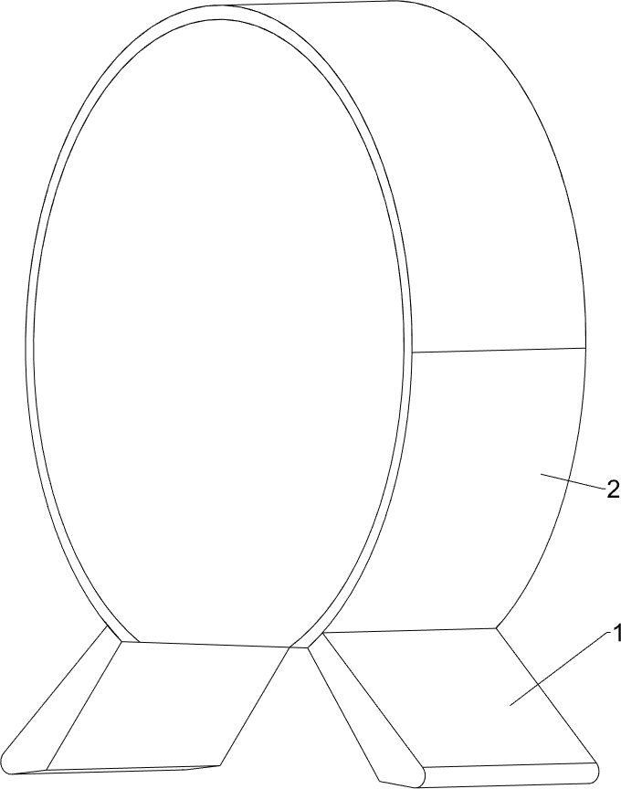
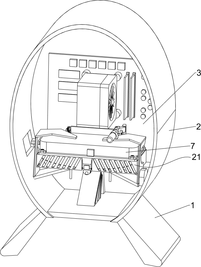
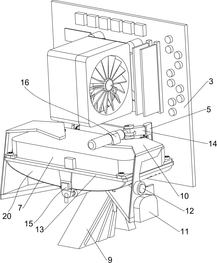
[0040] A kind of computer with graphics card protection function, refer to Figure 1-Figure 10 , including a foot 1, a chassis 2, a main board 3, a socket 4, a locking pin 5, a pin 6, a graphics card 7, an output line 8, a fixing seat 9, a fixing frame 10, a control box 11, an unlock button 12, and a first mounting plate 13 , dial block 14, pull-out component 15, unlocking component 16 and protection component 17, chassis 2 is arranged between the upper part of leg 1 on the left and right sides, the rear side of the inner wall of chassis 2 is provided with mainboard 3, and the front side lower part of mainboard 3 is provided with Socket 4 is arranged, and the right side rotation type of socket 4 is provided with locking pin 5, and locking pin 5 has elasticity, and the inner bottom rear side of cabinet 2 is welded with fixed seat 9, and the left and right sides upper part of fixed seat 9 is all provided with fixed frame 10 , the lower part of the right side of the fixed frame 1...

Embodiment 2

[0046] On the basis of embodiment 1, refer to Figure 11 and Figure 12 , also includes a protective assembly 18, the protective assembly 18 includes a connecting plate 181, a rotating rod 182, a third gear 183, an L-shaped plate 184, a sponge pad 185, a guide seat 186, a square bar 187, a second rack 188, elastic Rope 189 and baffle plate 1810, the left side bottom of socket 4 is welded with connecting plate 181, and the top front side of connecting plate 181 is provided with rotating rod 182, and the left side of rotating rod 182 is provided with the 3rd gear 183, and the top of socket 4 The rotary type is provided with an L-shaped plate 184, the left side of the L-shaped plate 184 is connected with the right side of the rotating rod 182, and the inner top of the L-shaped plate 184 is provided with a sponge pad 185, and the downward rotation of the sponge pad 185 will block the socket 4, thereby enabling The socket 4 is protected, the top of the connecting plate 181 is weld...


PUM


Abstract

The invention relates to a computer, in particular to a computer with a graphics card protection function. The invention aims to provide a computer with a graphics card protection function, which can automatically plug and pull a graphics card. The computer with the display card protection function comprises supporting legs, a case, a mainboard, a socket, a locking pin, a fixing base and the like, the case is arranged between the upper portions of the supporting legs on the left side and the right side, the mainboard is arranged on the rear side of the inner wall of the case, the socket is arranged on the lower portion of the front side of the mainboard, the locking pin is rotationally arranged on the right side of the socket, and the locking pin has elasticity and is fixed to the fixing base. And a fixed seat is arranged on the rear side of the inner bottom of the case. The second electric push rod is used as a driving force to drive the locking pin to rotate rightwards to loosen the plug pin, and then the first electric push rod is used as a driving force to drive the display card and the plug pin to move back and forth, so that the plugging function of the display card is automatically completed, and the plug pin is prevented from being broken in the socket in the carrying process.

Description

technical field [0001] The invention relates to a computer, in particular to a computer with a graphics card protection function. Background technique [0002] When installing a fixed graphics card in a computer case, one end of the graphics card is generally fixed on the computer case, and the other end is suspended in the air. When the card body of the graphics card is long, the graphics card is prone to heat or bumps to cause damage. [0003] Patent application CN212723844U, publication date 20210316, discloses a computer case with graphics card protection function, including a case body, which is provided with a case side plate, a case middle plate, a main mounting seat, an auxiliary mounting seat, and a mounting recess in the case body. groove, heat dissipation component, installation through groove, graphics card and support plate, one end of the support plate is fixedly connected to the main installation seat, and the other end of the support plate is inserted into th...

Claims


Application Information

Patent Timeline
IPC IPC(8): G06F1/18
CPCG06F1/183
Inventor 王立梅
Owner 东营职业学院
Why Eureka
Try Eureka