Supercharge Your Innovation With Domain-Expert AI Agents!

Platform for measuring radial rigidity of main shaft

A platform and rigid technology, applied in the field of the platform for measuring the radial rigidity of the main shaft, can solve the problems of manual handling, time-consuming and laborious, inconvenient to adapt to measuring personnel of different heights, etc., and achieve the effect of increasing stability.

Pending Publication Date: 2022-05-17
因那智能装备(大连)有限公司
View PDF0 Cites 0 Cited by
  • Summary
  • Abstract
  • Description
  • Claims
  • Application Information

AI Technical Summary

Problems solved by technology

[0003] The spindle radial rigidity measurement platform in the prior art is inconvenient to adjust the height during use, and it is not convenient to adapt to measurement personnel of different heights. At the same time, the platform is not easy to move. When the platform needs to be moved, it needs to be manually carried, which is time-consuming and laborious. , we propose a platform for measuring the radial stiffness of the spindle to solve the above problems

Method used


Image

  • Platform for measuring radial rigidity of main shaft
  • Platform for measuring radial rigidity of main shaft
  • Platform for measuring radial rigidity of main shaft

Examples


Embodiment 1

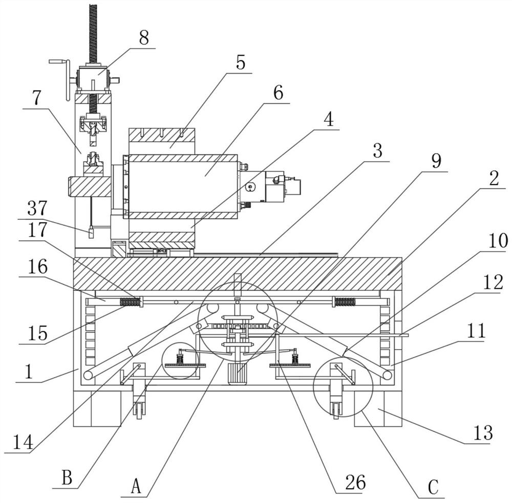
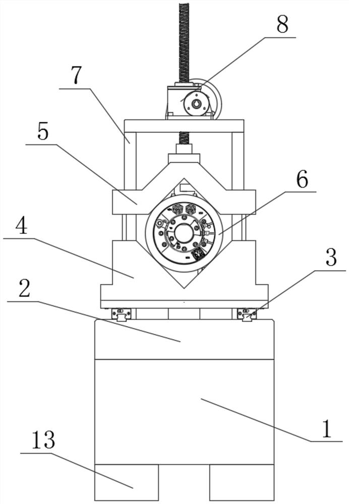
[0028] refer to Figure 1-5 , a platform for measuring the radial rigidity of the main shaft is proposed in this embodiment, including a platform 2, the bottom of the platform 2 is provided with a housing 1, and the top of the base 13 is fixed with a symmetrically arranged guide rail 3, and the number of guide rails 3 is two , the tops of the two guide rails 3 are slidingly connected with the same V-shaped base 4, the top of the V-shaped base 4 is slidably connected with a V-shaped buckle 5, the top of the V-shaped base 4 is provided with an auxiliary spindle 6, and the V-shaped base 4 is fixed to different sizes. The main shaft 6 of the rotating screw lifter 8 applies pressure to the hand wheel, and a dial indicator 37 is set below to detect the deformation. The top of the platform 2 is fixedly installed with a fixed frame 7, and the fixed frame 7 is fixedly installed with a screw screw lifter 8. The inboard of fixed frame 7 is fixedly equipped with dial indicator 37, is prov...

Embodiment 2

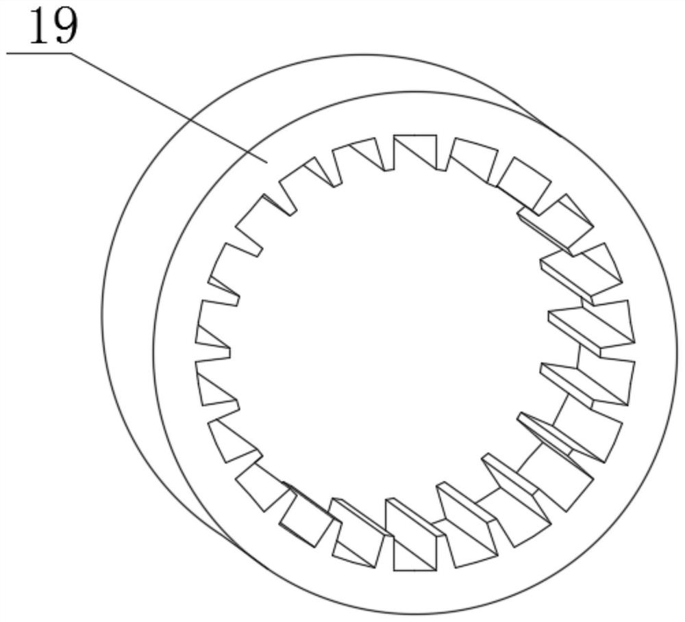
[0030]Power mechanism comprises motor 9, control lever 12, support 18, two connecting rings 19, two drive gears 20, push ring 21, pulling frame 22 and dial 39, motor 9 is fixedly installed on the inwall of shell 1, dial 39 is fixedly installed on the output shaft of the motor 9, and the two connecting rings 19 are connected to the bracket 18 in rotation, the control rod 12 is fixedly connected to the bracket 18 located on the right side, and the two driving gears 20 are fixedly connected to the two connecting rings 19 respectively , the push ring 21 is fixedly connected with the driving gear 20 at the lower position, and the pulling frame 22 is fixedly connected with the driving gear 20 at the upper position. 1, the top of the housing 1 is provided with a rectangular through hole, the bottom of the platform 2 is provided with a rectangular groove, and the outside of the pull frame 22 is in sliding contact with the inner wall of the rectangular through hole and the inner wall of...


PUM


Abstract

The invention belongs to the technical field of measuring platforms, particularly relates to a platform for measuring the radial rigidity of a main shaft, and aims to solve the problems that an existing platform for measuring the radial rigidity of the main shaft is inconvenient to adjust in height, inconvenient to adapt to measuring personnel with different heights, inconvenient to move, and time-consuming and labor-consuming due to the fact that manual carrying is needed when the platform needs to move. According to the scheme, the device comprises a platform, the bottom of the platform is provided with a shell, the top of the platform is fixedly provided with two symmetrically-arranged guide rails, the tops of the two guide rails are slidably connected with the same V-shaped base, the top of the V-shaped base is slidably connected with a V-shaped buckle, and the top of the V-shaped base is provided with an auxiliary spindle; the power mechanism is connected with the lifting self-locking mechanism or the moving self-locking mechanism, so that the function of the current shell can be selected, the platform can be lifted by the shell and then self-locked after being lifted, and the platform can be driven to move through the shell quickly and conveniently.

Description

technical field [0001] The invention relates to the technical field of measuring platforms, in particular to a platform for measuring the radial rigidity of a main shaft. Background technique [0002] Spindle rigidity is usually divided into axial rigidity and radial rigidity. It refers to the position change value after being stressed within the elastic deformation range. The common unit is μm / N, which means how much μm is deformed after loading a force of N; [0003] The spindle radial rigidity measurement platform in the prior art is inconvenient to adjust the height during use, and it is not convenient to adapt to measurement personnel of different heights. At the same time, the platform is not easy to move. When the platform needs to be moved, it needs to be manually carried, which is time-consuming and laborious. , we propose a platform for measuring the radial stiffness of the spindle to solve the above problems. Contents of the invention [0004] Based on the back...

Claims


Application Information

Patent Timeline
IPC IPC(8): G01M13/04
CPCG01M13/04
Inventor 孙海仁张京城
Owner 因那智能装备(大连)有限公司
Features
  • R&D
  • Intellectual Property
  • Life Sciences
  • Materials
  • Tech Scout
  • Unparalleled Data Quality
  • Higher Quality Content
  • 60% Fewer Hallucinations
Learn More