
Device and method for detecting pressure resistance of building pipe

A detection device and pipe material technology, which is applied in the directions of measuring device, analyzing materials, and using stable tension/pressure to test the strength of materials, etc., can solve the problems of low detection efficiency, achieve improved anti-slip performance, accurate pressure resistance detection, and ensure no offset effect

Pending Publication Date: 2022-05-24
广州中创建筑科技有限公司
View PDF0 Cites 0 Cited by
  • Summary
  • Abstract
  • Description
  • Claims
  • Application Information

AI Technical Summary

Problems solved by technology

At present, most of the methods of applying extrusion force to the middle end of the pipe and observing the deformation of the pipe are used to realize the pressure test of the pipe. However, in the actual detection process, it is necessary to adjust the space of the supporting mechanism and the extrusion mechanism in sequence according to the pipes of different lengths. location, which leads to low detection efficiency, so there are certain limitations

Method used


Image

  • Device and method for detecting pressure resistance of building pipe
  • Device and method for detecting pressure resistance of building pipe
  • Device and method for detecting pressure resistance of building pipe

Examples


Embodiment 1

[0037] According to an embodiment of the present invention,

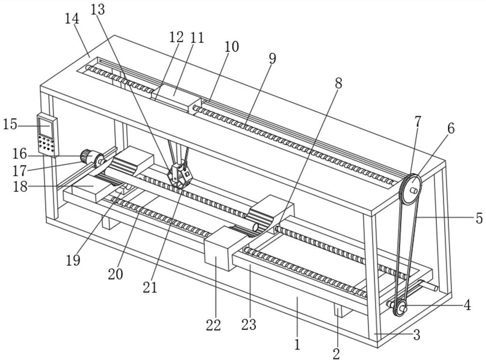
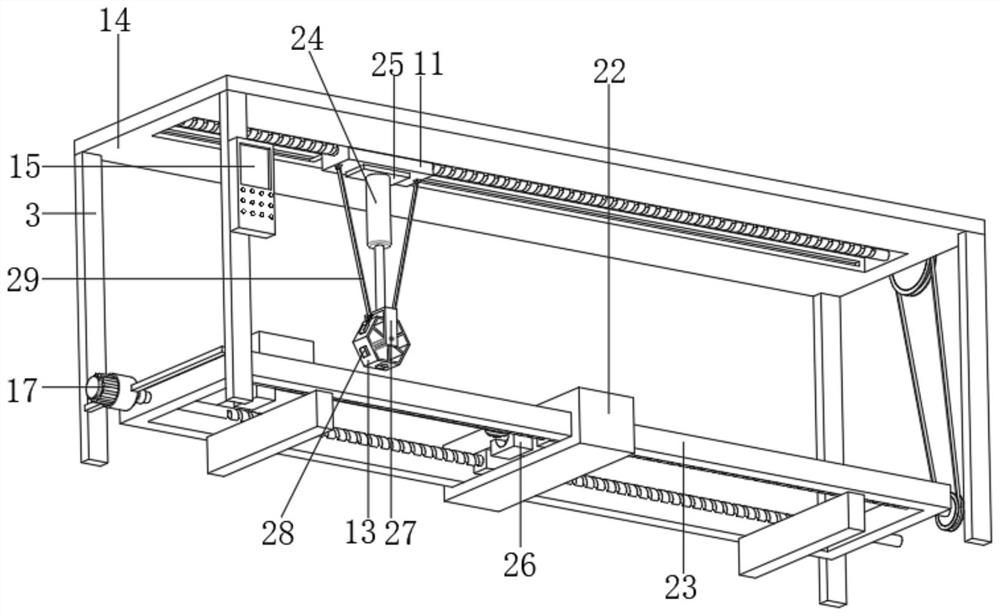
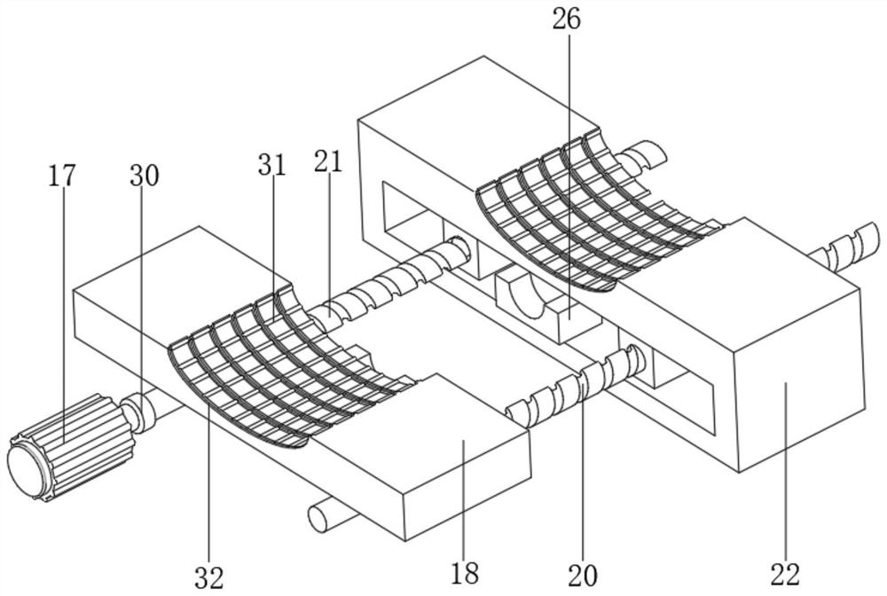
[0038] see Figure 1-7 , including the base plate 1 and the frame 23 located directly above the base plate 1, the opposite ends of the frame 23 and the base plate 1 are fixed with a support plate 2 by bolts, the frame 23 is installed with a moving adjustment mechanism, and the top of the base plate 1 The four corners of the outer wall are fixed with vertical columns 3 by bolts, and the top outer wall of the column 3 is fixed with the same top plate 14 by bolts. , the inner walls of both ends of the top notch are connected with the same top screw 9 through the bearing rotation, and the outer wall of one end of the top screw 9 is connected with a movable top block 11 through threads, and the inner walls of both sides of the top notch are provided with side grooves 10, and Both outer walls of the top plate 14 are welded with side slide plates 12 that are slidably connected to the side grooves 10, and the bottom outer ...

Embodiment 2

[0041] see figure 1 , figure 2 , Figure 4 , the adjustable extrusion mechanism includes a pressure sensor one 25 fixedly installed on the bottom outer wall of the moving top block 11, and the bottom end of the pressure sensor one 25 is fixedly installed with a hydraulic top rod 24, and the end of the extension rod of the hydraulic top rod 24 is fixed by bolts There is a U-shaped frame 27, and the U-shaped frame 27 is rotatably connected with a shaft through a bearing, the outer wall of the shaft is keyed with an inner connecting rib 33, and the end of the inner connecting rib 33 is fixed with the same hexagonal turret 13 by bolts , the outer wall of the hexagonal turret 13 is welded with arc groove pressing blocks 28, and the length of the arc groove pressing blocks 28 increases in turn. Both sides of the outer wall of the bottom are connected with fixed connecting rods 29 through hinges, and the ends of the fixed connecting rods 29 are provided with connecting holes match...

Embodiment 3

[0044] see Figure 1-2 , the opposite side of one end of the column 3 is fixed with a clamp rod 16 by bolts, and the inner wall of the clamp rod 16 is fixedly installed with a drive motor 17, and the output shaft of the drive motor 17 is fixedly connected with a torque sensor 30, and the other side of the torque sensor 30 is fixed. One end is fixedly connected with the second threaded screw rod 21 , and the control panel 15 is fixed with bolts on the side of the column 3 close to the clamp rod 16 .

[0045] The torque sensor 30 provided can provide the torque when the driving motor 17 operates, increase the types of detection data, and improve the detection accuracy.


PUM


Abstract

The invention discloses a building pipe pressure resistance detection device and method, and the device comprises a pedestal plate and a frame located right above the pedestal plate, the two ends of one side, opposite to the pedestal plate, of the frame are fixedly provided with supporting plates through bolts, and the frame is provided with a mobile adjusting mechanism. Vertically-arranged stand columns are fixed to the four corners of the outer wall of the top of the base plate through bolts, the same top plate is fixed to the outer walls of the tops of the stand columns through bolts, the top plate is provided with a follow-up mechanism, the follow-up mechanism comprises a top notch formed in the top plate, and the inner walls of the two ends of the top notch are rotationally connected with the same top screw through bearings; and the outer wall of one end of the top screw rod is in threaded connection with a movable top block, and side grooves are formed in the inner walls of the two sides of the top groove opening correspondingly. According to the invention, the movable top block is always positioned between the fixed support block and the movable support block, and the movable top block does not need to be independently adjusted and calibrated, so that rapid and accurate pressure resistance detection on the pipe is facilitated.

Description

technical field [0001] The invention relates to the field of construction pipe material detection, in particular to a construction pipe material pressure-resistant energy detection device and a detection method. Background technique [0002] Construction engineering refers to the planning, survey, design and construction, completion and other technical work and completed engineering entities for the new, reconstructed or expanded buildings and ancillary structures and facilities, as well as the installation engineering of its supporting lines, pipelines and equipment . Pipes are necessary materials for construction projects, commonly used are water supply pipes, drainage pipes, gas pipes, heating pipes, wire conduits, rainwater pipes, etc. With the development of science and technology, the pipes used in home decoration have also experienced the development process of ordinary cast iron pipes → cement pipes → reinforced concrete pipes, asbestos cement pipes → ductile iron p...

Claims


Application Information

Patent Timeline
Patent Type & Authority Applications(China)
IPC IPC(8): G01N3/12G01N3/02G01N3/04
CPCG01N3/12G01N3/02G01N3/04G01N2203/0019G01N2203/0048G01N2203/0274G01N2203/04
Inventor 邹锦新
Owner 广州中创建筑科技有限公司
Learn More