
Pit pressure folding resistance detection equipment for new material

A technology for testing equipment and new materials, applied in the direction of analyzing materials, testing material strength by applying stable bending force, testing material strength by applying stable tension/pressure, etc. It can solve the problem of moving new materials and not being able to pit new materials Compression and folding test and other issues to achieve the effect of preventing damage

Pending Publication Date: 2021-04-23
南京溢莱毅电子科技有限公司
View PDF1 Cites 0 Cited by
  • Summary
  • Abstract
  • Description
  • Claims
  • Application Information

AI Technical Summary

Problems solved by technology

[0005] In order to overcome the shortcomings of the current method of inspecting new materials that cannot continuously move new materials and simultaneously test the pit pressure and folding resistance of new materials, the technical problem to be solved: provide a method that can simultaneously pit pressure and fold resistance testing, and continuously conduct Pit pressure and folding test equipment for mobile new materials

Method used


Image

  • Pit pressure folding resistance detection equipment for new material
  • Pit pressure folding resistance detection equipment for new material
  • Pit pressure folding resistance detection equipment for new material

Examples


Embodiment 1

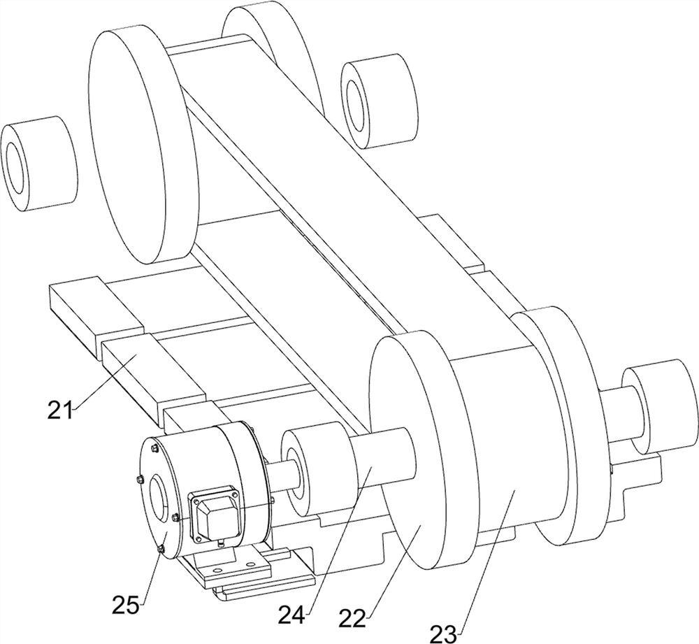
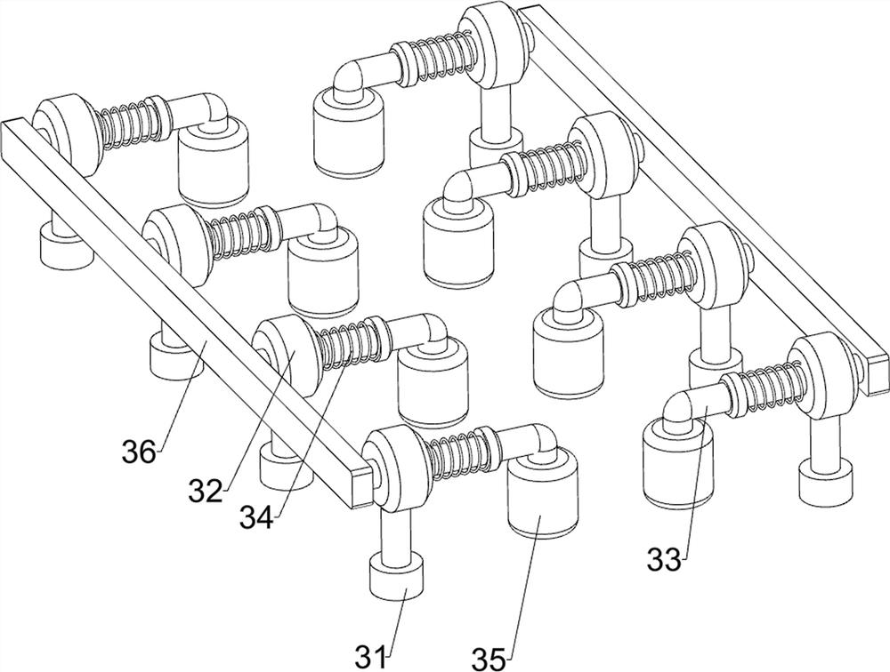
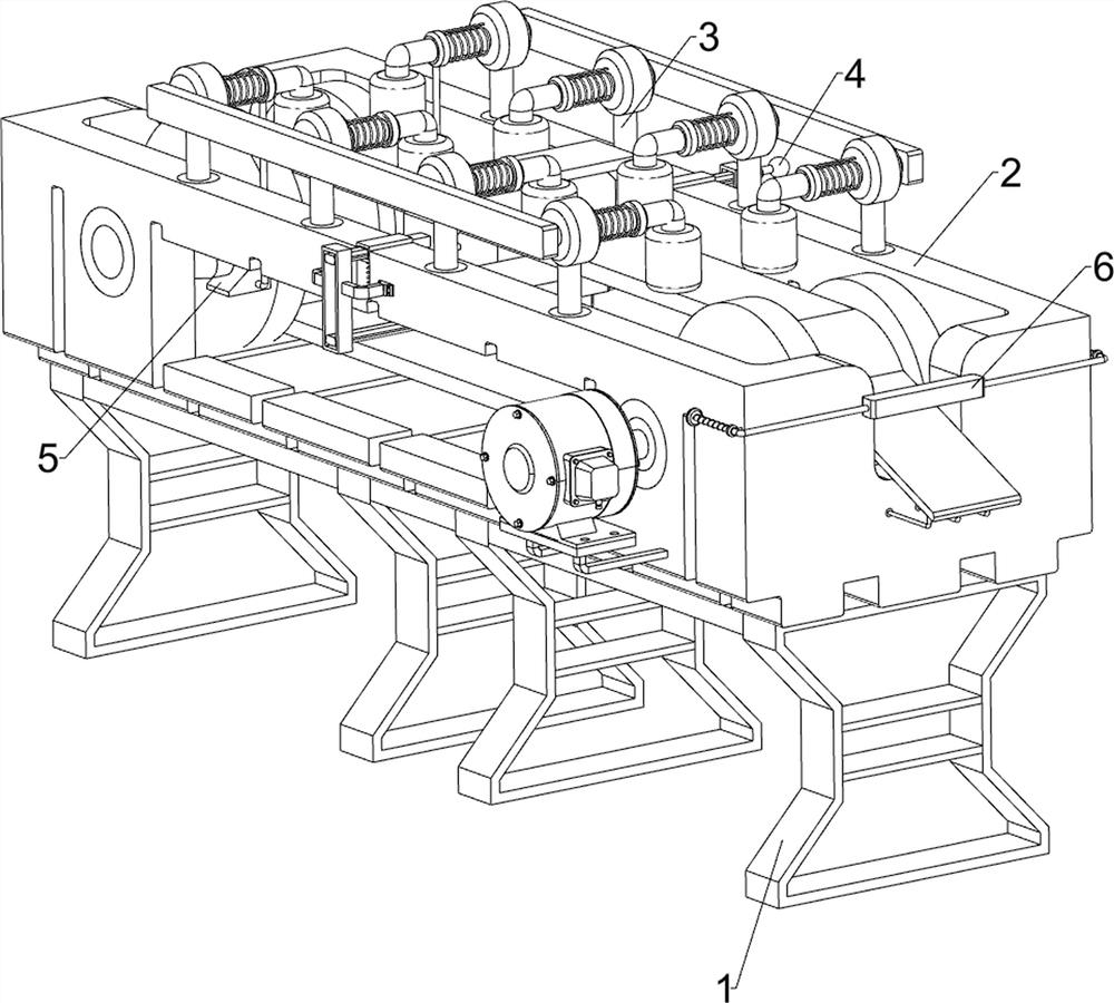
[0022] Pit pressure and folding test equipment for a new material, such as Figure 1-Figure 6 As shown, it includes a base 1, a transmission component 2, a compression component 3 and a bending component 4. The base 1 is used to install the entire device. The upper part of the base 1 is provided with a transmission component 2 that provides power for transmission. A compression component 3 that resists compression by sliding, and a bending component 4 that bends by sliding is provided in the middle of the transmission component 2 .

[0023] When a new material needs to be inspected, the staff first places the new material on the conveying component 2, and then starts the conveying component 2 to transmit the new material. At the same time, the new material and the bending component 4 are continuously inspected, and then When the material is moved to an appropriate position, the staff moves the bending assembly 4 to monitor the compression resistance of the new material. When t...

Embodiment 2

[0031] On the basis of Example 1, such as figure 1 and Figure 5 As shown, it also includes a push assembly 5, the push assembly 5 includes a push block 51, a connecting rod 52 and a wedge block 53, the rotating rod 24 is provided with a push block 51, there are two connecting rods 52, and the rightmost L-shaped The bottom of the bar 33 is welded with a connecting rod 52, and the tail end of the connecting rod 52 is fixedly connected with a wedge-shaped block 53 by screws, and the push block 51 cooperates with the wedge-shaped block 53.

[0032] When the rotating rod 24 rotates, it drives the push block 51 to rotate, pushes the wedge block 53 to move inwardly, drives the connecting rod 52 to move inwardly, and then drives the L-shaped bar 33 to move inwardly. When the push block 51 and the wedge block 53 are separated, Under the action of the L-shaped rod 33, the connecting rod 52 and its upper device are moved outwards and reset, so that the new material can be automatically...


PUM


Abstract

The invention relates to detection equipment, in particular to pit pressure folding resistance detection equipment for a new material. The pit pressure folding resistance detection equipment for the new material can detect pit pressure folding resistance at the same time and continuously move. The pit pressure folding resistance detection equipment for the new material comprises a base for mounting the whole device; the conveying assembly is installed on the base and provides power for conveying; the pressure-resistant assembly is mounted on the conveying assembly and resists pressure in a sliding manner; and the bending assembly is installed on the conveying assembly and conducts bending in a sliding mode. Through cooperation of the conveying wheel and the conveying belt, a new material can be quickly conveyed to a proper position, through cooperation of the L-shaped rod and the extrusion wheel, compression resistance detection can be quickly carried out on the new material, through cooperation of the first pressing block and the second pressing block, bending detection can be carried out on the new material, and through cooperation of the push block and the wedge-shaped block, the detection precision is improved. The compression resistance detection can be automatically carried out on a new material.

Description

technical field [0001] The invention relates to a detection device, in particular to a pit pressure and folding resistance detection device for a new material. Background technique [0002] New materials refer to newly developed or developing structural materials with excellent properties and functional materials with special properties. Structural materials mainly use their mechanical properties such as strength, toughness, hardness, and elasticity. After testing the new materials, the staff need to conduct a pit pressure and folding test on the new materials. [0003] Patent Publication No. CN110987652A discloses a bending strength testing device for new material testing, including a base plate, a placement seat, a bearing and a nut, the upper end surface of the base plate is provided with a placement seat, and the scale plate is fixed on the base plate. On the end face, the first connecting rod is connected to the side of the work frame, the contact column is installed o...

Claims


Application Information

Patent Timeline
Patent Type & Authority Applications(China)
IPC IPC(8): G01N3/08G01N3/20G01N3/02
CPCG01N3/02G01N3/08G01N3/20G01N2203/0019G01N2203/0023
Inventor 李斯超
Owner 南京溢莱毅电子科技有限公司
Learn More