Bottom protective device of lift shaft

A technology for protective devices and elevator shafts, applied in transportation, packaging, elevators, etc., can solve problems such as difficult maintenance, serious safety problems, complicated installation, etc., and achieve the effects of avoiding disasters, clear and easy to understand structure, and simple structure

Pending Publication Date: 2018-10-16
SUZHOU DEAO ELEVATOR
View PDF0 Cites 2 Cited by
  • Summary
  • Abstract
  • Description
  • Claims
  • Application Information

AI Technical Summary

Problems solved by technology

[0002] With the emergence of more and more high-rise buildings, the application of elevators is more common, but the safety problem is serious, and the accidents are increasing, especially the falling accidents of elevator cabins and personnel. The impact is very strong, often endangering personal safety
When the control system falls out of control, the elevator will fall rapidly. In the prior art, the common solution is to use a mechanical speed limiter, that is, when the car is running, the steel wire connected to it drives the speed limiter pulley to rotate. At the threshold, the centrifugal arm on the pulley touches the safety switch and gives a fall signal. This method of using a mechanical speed limiter requires mechanical mechanisms such as steel wires, pulleys, centrifugal arms, and springs. The length of the steel wires is proportional to the height of the floor. It consumes a lot of materials, and there are also problems of complicated installation, which cause problems such as high cost and difficult construction. Moreover, in the current elevator system, the elevator keeps stopping at a certain position, which depends on the friction force of the brake of the traction machine. It is achieved by preventing the rotation of the motor. Once the brake fails, the car or counterweight will fall along the hoistway under the action of gravity
Once this situation occurs when the elevator leveling position opens the door to pass in and out of passengers, the resulting personal injury accident is very serious
[0003] Moreover, there is no anti-fall protection device at the bottom of many elevator shafts. The reason is that the existing anti-fall protection device has a complex structure, high cost, poor durability, and is difficult to maintain. Therefore, a protection device at the bottom of the elevator shaft is needed to further protect the elevator.

Method used


Image

  • Bottom protective device of lift shaft
  • Bottom protective device of lift shaft

Examples


Embodiment Construction

[0015] The following will clearly and completely describe the technical solutions in the embodiments of the present invention with reference to the accompanying drawings in the embodiments of the present invention. Obviously, the described embodiments are only some, not all, embodiments of the present invention. Based on the embodiments of the present invention, all other embodiments obtained by persons of ordinary skill in the art without making creative efforts belong to the protection scope of the present invention.

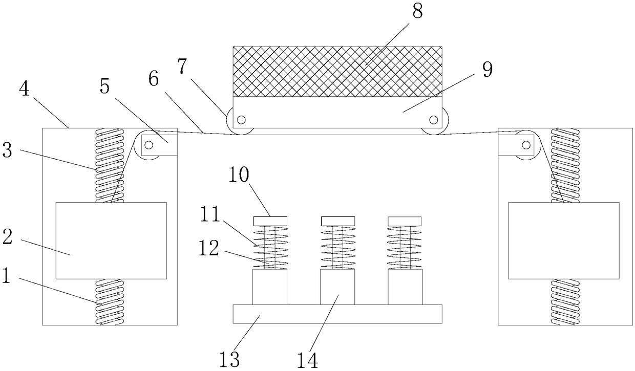
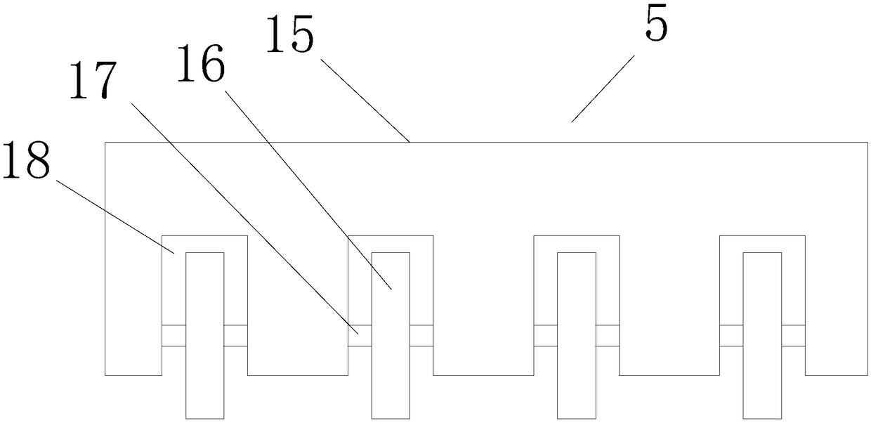
[0016] see Figure 1~2 , the present invention provides a technical solution: a bottom protection device for an elevator shaft, including a load-bearing plate 9, the load-bearing plate 9 is suspended above the steel cable 6, and load-bearing boxes 4 are arranged on the left and right sides of the load-bearing plate 9 A heavy block 2 is suspended in the load-bearing box 4, and an upper buffer spring 3 is fixedly connected between the upper end surface of the he...


PUM


Abstract

The invention discloses a bottom protective device of a lift shaft. The bottom protective device of the lift shaft comprises a bearing plate. When a lift falls, the lift can fall to the upper side ofthe bearing plate, the upper end face of the bearing plate is provided with a buffering mat, so that direct impact is avoided, steel cables on the lower side of the bearing plate can be tensioned at the moment, heavy blocks in bearing boxes are pulled to move upwards through guide devices, upper buffering springs can shrink at the moment, lower buffering springs can be straightened, and then partof falling force is absorbed. In addition, when the bearing plate makes contact with supporting blocks, hydraulic cylinders and buffering springs can generate upward supporting force, so that the falling speed is further lowered. In this way, the bottom protective device of the lift shaft is simple in structure and clear and simple in constitution, decomposes, disperses and absorbs the falling force of the lift and prevents disasters.

Description

technical field [0001] The invention relates to the technical field of an elevator shaft bottom protection device, in particular to a bottom protection device for an elevator shaft. Background technique [0002] With the emergence of more and more high-rise buildings, the application of elevators is more common, but the safety problem is serious, and the accidents are increasing, especially the falling accidents of elevator cabins and personnel. The impact force is very large, often endangering personal safety. When the control system falls out of control, the elevator will fall rapidly. In the prior art, the common solution is to use a mechanical speed limiter, that is, when the car is running, the steel wire connected to it drives the speed limiter pulley to rotate. At the threshold, the centrifugal arm on the pulley touches the safety switch and gives a fall signal. This method of using a mechanical speed limiter requires mechanical mechanisms such as steel wires, pulley...

Claims


Application Information

Patent Timeline
Patent Type & Authority Applications(China)
IPC IPC(8): B66B5/28
CPCB66B5/282
Inventor 王应刘开双
Owner SUZHOU DEAO ELEVATOR
Why Eureka
Try Eureka