
Fuel nozzle and aero-engine

A technology for aero-engines and fuel nozzles, applied in the field of aero-engines, can solve problems such as thermal vibrations, achieve the effects of reducing vibration energy levels, reducing vibration amplitudes, and avoiding excessively high dynamic stress levels of oil collecting ring supports

Active Publication Date: 2022-05-27
AECC COMML AIRCRAFT ENGINE CO LTD
View PDF4 Cites 0 Cited by
  • Summary
  • Abstract
  • Description
  • Claims
  • Application Information

AI Technical Summary

Problems solved by technology

Fuel nozzles face serious challenges in operation due to thermal vibrations

Method used


Image

  • Fuel nozzle and aero-engine
  • Fuel nozzle and aero-engine
  • Fuel nozzle and aero-engine

Examples


Embodiment Construction

[0032] The technical solutions in the embodiments will be clearly and completely described below with reference to the accompanying drawings in the embodiments of the present invention. Obviously, the described embodiments are only some, but not all, embodiments of the present invention. Based on the embodiments of the present invention, all other embodiments obtained by persons of ordinary skill in the art without creative efforts shall fall within the protection scope of the present invention.

[0033] In the description of the present invention, it should be understood that the terms "center", "portrait", "horizontal", "front", "rear", "left", "right", "vertical", "horizontal", The orientation or positional relationship indicated by "top", "bottom", "inner", "outer", etc. is based on the orientation or positional relationship shown in the drawings, and is only for the convenience of describing the present invention and simplifying the description, rather than indicating or ...


PUM


Abstract

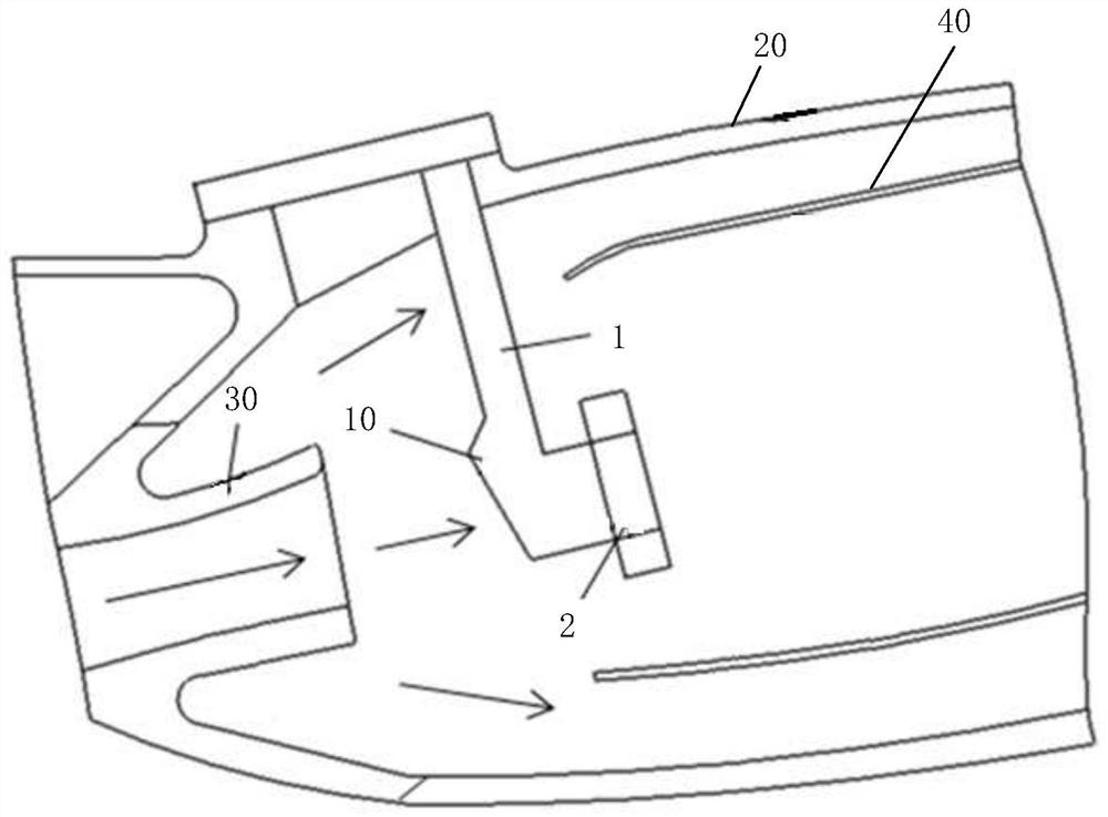
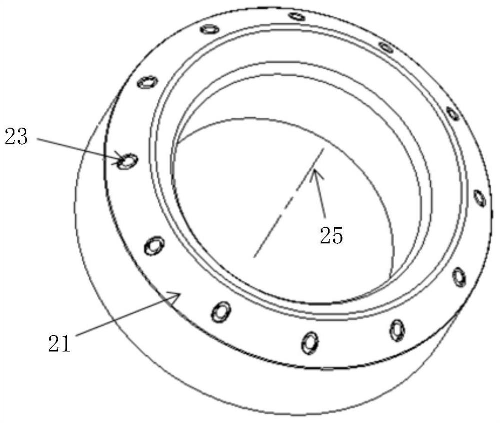
The invention relates to a fuel nozzle and an aero-engine which are used for relieving the thermal vibration problem of the fuel nozzle. The fuel nozzle comprises a spray rod and a nozzle body, the spray head comprises a shell and an oil collecting ring, the shell is annular, the oil collecting ring is arranged between the inner wall and the outer wall of the shell, the oil collecting ring is communicated with the spray rod, the oil collecting ring is provided with a nozzle extending towards the outer wall of the shell, and the nozzle penetrates through the outer wall of the shell; a protruding block is arranged on the wall face, close to the outer wall of the shell, of the oil collecting ring. When the oil collecting ring generates local resonance, the vibration amplitude can be effectively reduced, so that local vibration of the oil collecting ring is restrained, the vibration energy level of the oil collecting ring is reduced, the situation that the supporting dynamic stress level of the oil collecting ring is too high due to resonance of the oil collecting ring is avoided, and the high-cycle fatigue life of the fuel nozzle is prolonged.

Description

technical field [0001] The invention relates to the field of aero-engines, in particular to a fuel nozzle and an aero-engine. Background technique [0002] The fuel nozzle is located in the front section of the combustion chamber and is in a high temperature and high pressure environment during operation. There are two main sources of heat for the fuel nozzle. One is that the high-temperature gas entering the combustion chamber through the compressor directly blows the fuel nozzle, causing the nozzle rod and head to be heated. The high temperature flame produces heat radiation to the fuel nozzle, and the maximum temperature of the fuel nozzle head can reach 900K-1000K. Fuel nozzles are not only affected by high temperature, but also in a complex vibration environment. The materials used in fuel nozzles are mainly superalloys, and the changes in their mechanical properties at high temperatures will lead to different degrees of forward movement of the vibration frequencies of...

Claims


Application Information

Patent Timeline
Patent Type & Authority Applications(China)
IPC IPC(8): F23R3/28
CPCF23R3/283F23R2900/00013Y02T50/60
Inventor 陈赫邓向阳陈浩
Owner AECC COMML AIRCRAFT ENGINE CO LTD
Learn More