An auxiliary ultrasonic vibration hammering device for laser additive manufacturing and its application method

A technology of ultrasonic vibration and laser additive materials, which is applied in the direction of additive manufacturing, additive processing, and improvement of process efficiency. It can solve problems such as air holes, gaps and cracks, decreased manufacturing quality of formed parts, and poor surface flatness of formed parts. , to achieve the effect of improving flatness, reducing the probability of appearance, and enhancing plasticity

Active Publication Date: 2018-11-23
SHENYANG AEROSPACE UNIVERSITY
View PDF9 Cites 0 Cited by
  • Summary
  • Abstract
  • Description
  • Claims
  • Application Information

AI Technical Summary

Problems solved by technology

[0005] However, in the rapid melting and solidification process of the alloy, the solidification of the molten pool is achieved by heat conduction to the substrate of the formed part and the deposited layer. At the microscopic level, the top interface of the molten pool is similar to an ellipsoid, and the bottom interface of the molten pool is approximately horizontal. , the temperature of the molten pool interface changes from the bottom of the molten pool to the top of the molten pool, and the temperature gradient changes greatly, which will lead to a large thermal stress in the part that has been solidified and formed, and there is also a structural stress in the material phase transition, and As a result, air holes, gaps and cracks may appear at any time, and the surface flatness of the formed part is poor, which in turn leads to a decline in the manufacturing quality of the formed part

Method used


Image

  • An auxiliary ultrasonic vibration hammering device for laser additive manufacturing and its application method

Examples


Embodiment Construction

[0025] The present invention will be further described in detail below in conjunction with the accompanying drawings and specific embodiments.

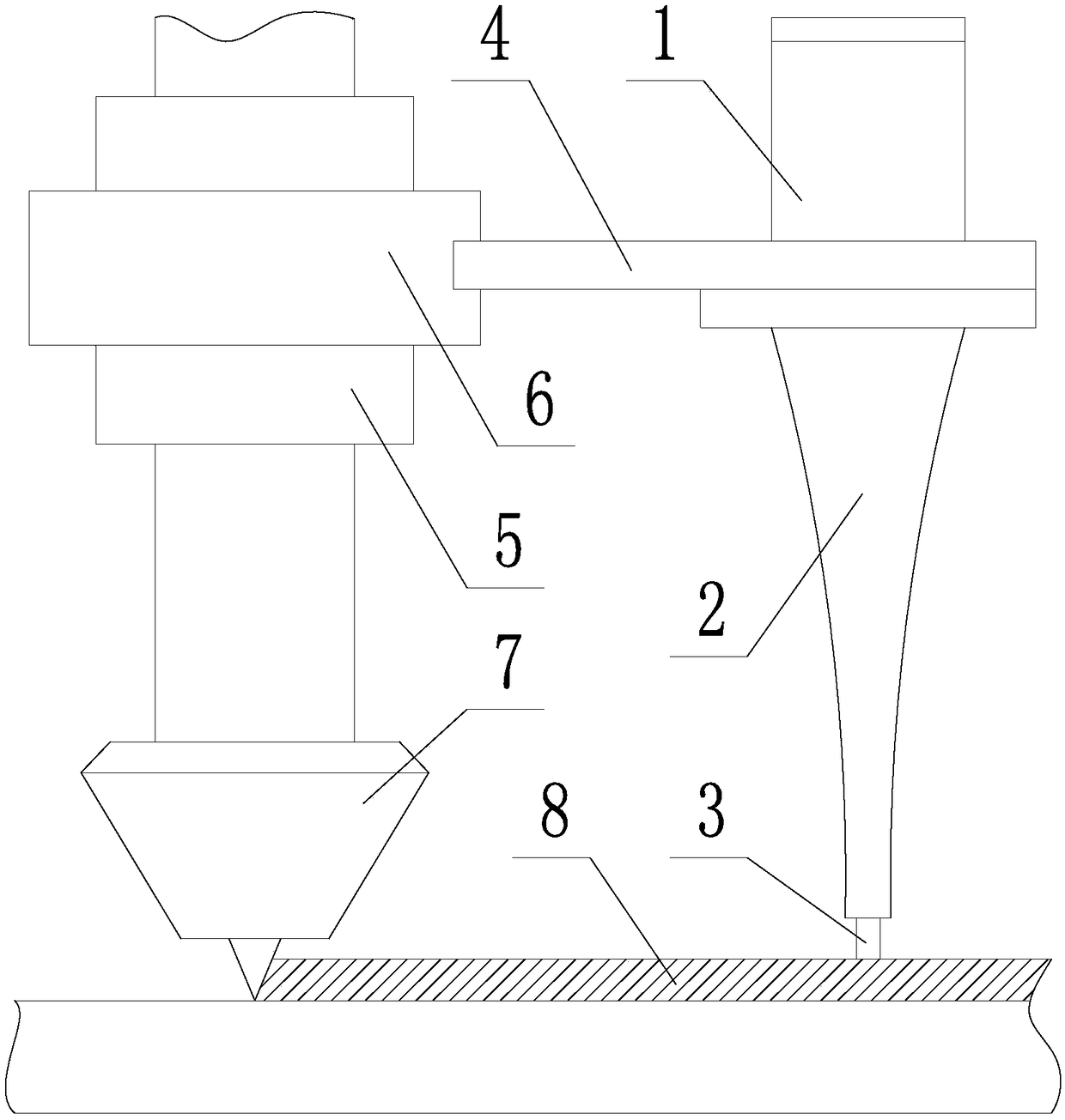
[0026] like figure 1 As shown, an auxiliary ultrasonic vibration hammering device for laser additive manufacturing, including an ultrasonic transducer 1, a horn 2, a hammering head 3, a follower connecting frame 4, a fixed sleeve 5 and a rotary sleeve 6; The fixed sleeve 5 is fixedly connected to the laser head 7. The rotary sleeve 6 is set on the fixed sleeve 5. The rotary sleeve 6 has a degree of freedom of rotation relative to the fixed sleeve 5. There is a locking structure between the rotary sleeve 6 and the fixed sleeve 5. The rotary sleeve The centerline of rotation of 6 coincides with the axial centerline of laser head 7; one end of the moving connecting frame 4 is fixedly connected to the rotating sleeve 6, and the ultrasonic transducer 1 is fixed on the other end of the moving connecting frame 4, so The horn 2 is installed ...


PUM


Abstract

An auxiliary ultrasonic vibration hammering device for laser additive manufacturing and its use method, the device includes an ultrasonic transducer, a horn, a hammering head, a follower connecting frame, a fixed sleeve and a rotary sleeve; the fixed sleeve is fixedly connected to the laser head , the rotary sleeve has a degree of freedom of rotation relative to the fixed sleeve, and there is a locking structure between the two; one end of the follow-up connecting frame is fixedly connected to the rotary sleeve, and the other end is fixed with an ultrasonic transducer, and the horn is installed on the ultrasonic transducer. The lower part of the device, the hammer head is fixed at the bottom of the horn. The steps of the method are as follows: rotate the rotary sleeve so that the hammer head is located on the scanning path of the laser head, and lock the rotary sleeve; the laser head performs deposition operations, starts the ultrasonic transducer, transmits the ultrasonic vibration to the hammer head, and through the hammer head Ultrasonic vibration hammering is performed on the deposited layer; when the laser head moves to the boundary of the formed part, the locking of the rotary sleeve is released, and the rotary sleeve is rotated 180° and then locked again, and the ultrasonic vibration hammering is continued on the deposited layer; so reciprocating until the formed part is completed manufacturing.

Description

technical field [0001] The invention belongs to the technical field of laser additive manufacturing, and in particular relates to an auxiliary ultrasonic vibration hammering device for laser additive manufacturing and a use method thereof. Background technique [0002] Laser Additive Manufacturing technology (Laser Additive Manufacturing, referred to as LAM, commonly known as 3D printing technology), uses alloy powder as raw material, melts the alloy powder in situ through high-power laser, and makes the alloy powder in the molten state solidify rapidly and gradually deposition to make solid parts. [0003] The principle of laser additive manufacturing technology is as follows: first, use computer 3D software to design a 3D model of the part, and then perform layered slice processing on the 3D model in the computer to discretize the 3D model into a series of 2D layers, and finally use laser Scan and add alloy powder layer by layer, and finally convert the 3D model part into...

Claims


Application Information

Patent Timeline
Patent Type & Authority Patents(China)
IPC IPC(8): B22F3/105B33Y30/00B33Y10/00
CPCB33Y10/00B33Y30/00B22F2999/00B22F10/00B22F12/00B22F10/25B22F2202/01Y02P10/25
Inventor 钦兰云刘佳蓬杨光任宇航尚纯王伟何波王霞王维
Owner SHENYANG AEROSPACE UNIVERSITY
Why Eureka
Try Eureka