Capacitive sensor having flexible polymeric conductors

a polymer conductor, capacitive sensor technology, applied in the direction of fixed capacitor details, feed-through capacitors, instruments, etc., can solve the problems of reducing the sensitivity of capacitive sensors, and affecting the detection efficiency of capacitive sensors. , to achieve the effect of improving sensitivity, enlarging the cross-section, and changing the shap

Inactive Publication Date: 2007-05-08
SCHLEGEL
View PDF43 Cites 72 Cited by
  • Summary
  • Abstract
  • Description
  • Claims
  • Application Information

AI Technical Summary

Benefits of technology

[0013]The present capacitive sensor includes a first elongate conductive polymer, a spaced apart second elongate conductive polymer and an intermediate non conductive spacing web substantially fixing the separation distance between the conductive polymers. Thus, the capacitive sensor can include a sensor electrode and a ground electrode arranged spaced apart from each other with a fixed separation distance between the two electrodes. The spacing web substantially precludes displacement of the electrodes with respect to each other during installation of the capacitive sensor about a curvilinear path. Thus, the separation distance is substantially constant along the length of the sensor. Further, by employing polymeric conductors, the present capacitive sensor can bend about any axis without requiring excessive force or resulting damage to the sensor.
[0016]Preferably, the body of the capacitive sensor is, at least partially, made of an electrically non conductive material to insulate the sensor electrode with respect to the ground electrode. The sensor electrode and / or the ground electrode can be formed as polymeric conductors and shaped into any of a variety of cross-sections, thus providing for enlarging their cross-section and changing their shape. The enlarged cross-section provides a higher sensitivity, while the electrode shape allows the change in size and orientation of the sensing region.

Problems solved by technology

However, there exists the danger that foreign matter or a body part can be caught between the upper edge of the window and the window frame upon closing, thus leading to injuries.
These trapping protectors require physical contact and cause significant squeezing of a body part caught between the upper edge of the window and the window frame.
The capacitive sensors can only detect dielectric materials.
However, wood, plastic or any other non conductive material cannot be detected as they do not cause a change of capacity.

Method used


Image

  • Capacitive sensor having flexible polymeric conductors
  • Capacitive sensor having flexible polymeric conductors
  • Capacitive sensor having flexible polymeric conductors

Examples


Embodiment Construction

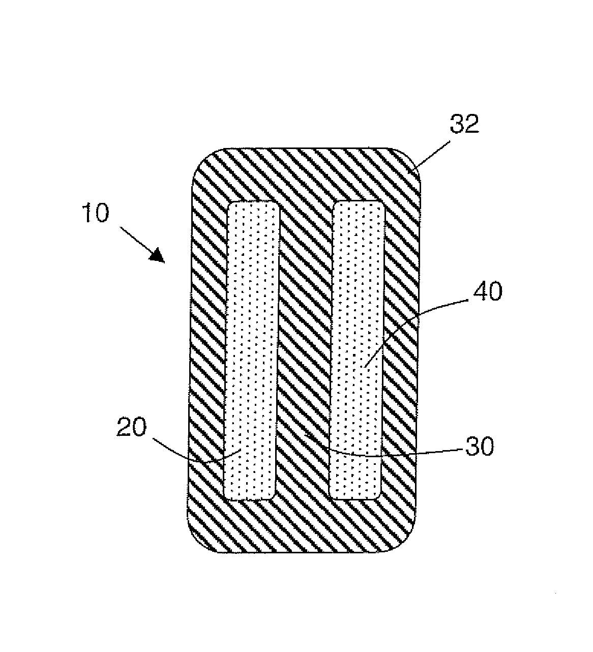
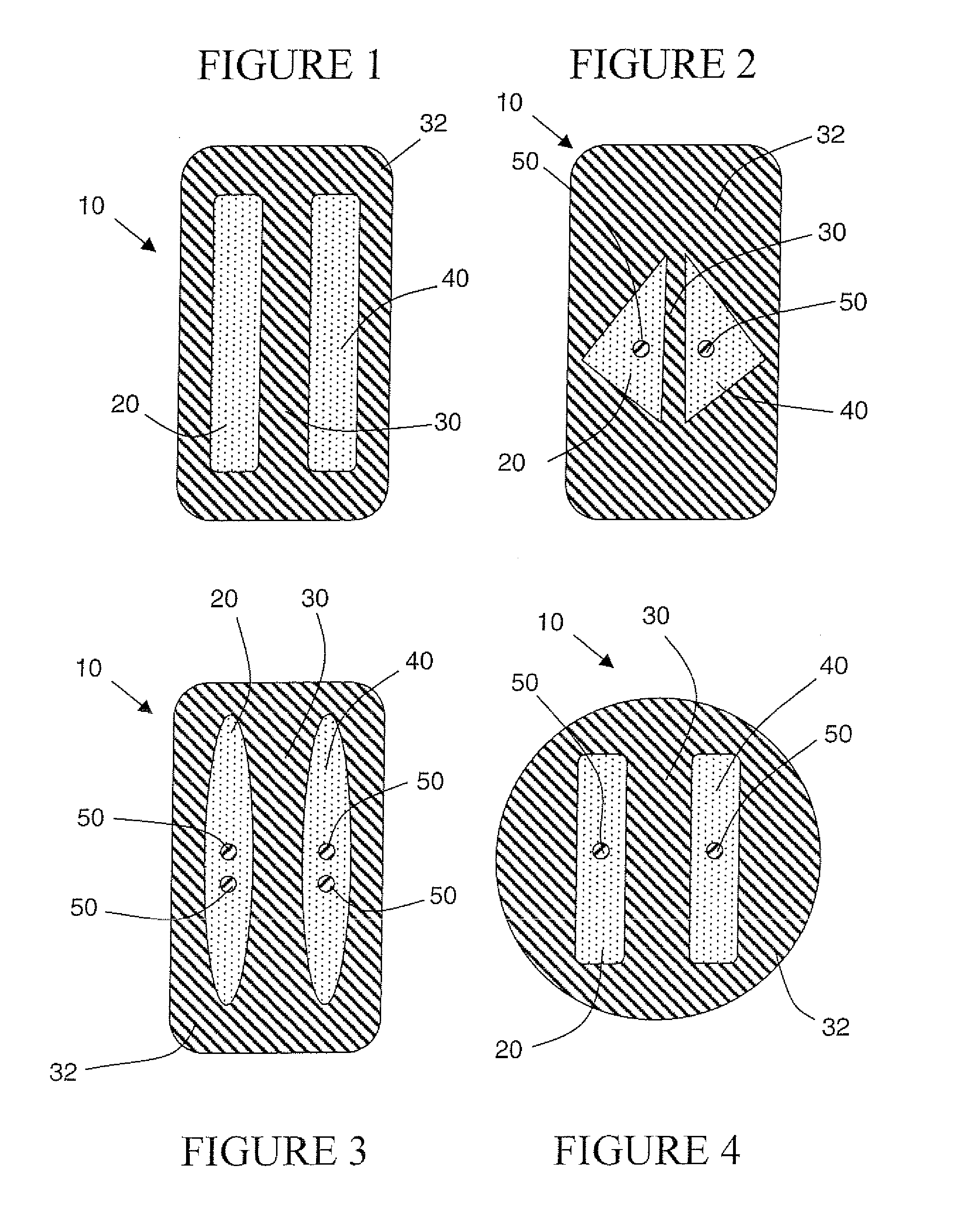
[0028]Referring to FIGS. 1–4, a capacitive sensor 10 includes a first polymeric conductor 20 and second polymeric conductor 40 and an intermediate non conductive (insulating) web 30, wherein a separation distance between the first and the second polymeric conductor is substantially fixed.

[0029]The polymeric conductors 20, 40 can have any of a variety of cross sections. For example, the cross-sections can include, but are not limited to rectangular, square, round, oval, curvilinear, or multifaceted. It is also understood the polymeric conductors 20, 40 can have cross-sections defined by any of a variety of letters such as, but not limited to “C”, “W”, “U” or “L”. The polymeric conductors 20, 40 can be symmetrical or asymmetrical relative to the web 30. A preferred cross-section is rectangular, wherein the height of the polymeric conductor is at least twice and can be as many as 10 times the width of the conductor as seen in FIG. 1.

[0030]In certain configurations, it is desirable for ...


PUM

PropertyMeasurementUnit
radiusaaaaaaaaaa
diameteraaaaaaaaaa
forceaaaaaaaaaa

Abstract

A capacitive sensor having a first and a second polymeric conductor are embedded within a non conducting body, wherein the body maintains a fixed separation distance between the first and the second polymeric conductor. The body can include a non conducting web, wherein the web substantially precludes variation in the spacing of the polymeric conductors during use in the intended operating environment.

Description

CROSS-REFERENCE TO RELATED APPLICATIONS[0001]Not applicable.STATEMENT REGARDING FEDERALLY SPONSORED RESEARCH OR DEVELOPMENT[0002]Not applicable.REFERENCE TO A “SEQUENCE LISTING”[0003]Not applicable.BACKGROUND OF THE INVENTION[0004]1. Field of the Invention[0005]The present invention relates to a capacitive sensor, and more particularly, to a capacitive sensor having a pair of spaced polymeric conductors, wherein a substantially constant spacing between the polymeric conductors is maintained by a non conductive web.[0006]In a particular configuration, the present invention relates to a trapping protector for detecting the presence of an object in a sensing region. The trapping protector can be employed in a weatherseal, and comprises a capacitive sensor having a body, at least one polymeric conductor as a ground electrode and at least one polymeric conductor as a sensor electrode arranged in a spaced apart relation and embedded in the body, wherein an intermediate insulating web main...

Claims


Application Information

Patent Timeline
Patent Type & Authority Patents(United States)
IPC IPC(8): H01G4/005B60J10/00B60J10/79E05F15/00G01D5/24G01L1/14
CPCB60J10/00B60J10/06E05F15/46G01D5/2405G01L1/144E05Y2900/548B60J10/79
Inventor ROSENAU, KEITH W.
Owner SCHLEGEL
Why Eureka
Try Eureka