Display device

A display device, LED device technology, applied in the direction of identification devices, instruments, semiconductor devices, etc., to achieve the effects of excellent design and flexibility, excellent flexibility, and excellent display effect

Pending Publication Date: 2022-05-27
SAKATA INX
View PDF2 Cites 0 Cited by
  • Summary
  • Abstract
  • Description
  • Claims
  • Application Information

AI Technical Summary

Problems solved by technology

However, since the presence of the LED element is obvious even when it is not emitting light, it is desired to improve the design.

Method used


Image

  • Display device
  • Display device
  • Display device

Examples


Embodiment Construction

[0041] Hereinafter, a preferred embodiment of the display device according to the present invention will be described with reference to the accompanying drawings, but the present invention is not limited to the following one embodiment. In addition, it can change suitably in the range which does not deviate from the range which can exhibit the effect of this invention. Additionally, the use of the same reference numbers in different drawings indicates similar or identical items or features.

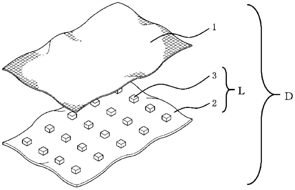
[0042] like figure 1 As shown, the display device D, which is one embodiment of the present invention, includes the LED device L and the porous material 1 . The LED device L is a device in which a plurality of LED elements 3 are soldered to one surface side of the flexible base material 2 .

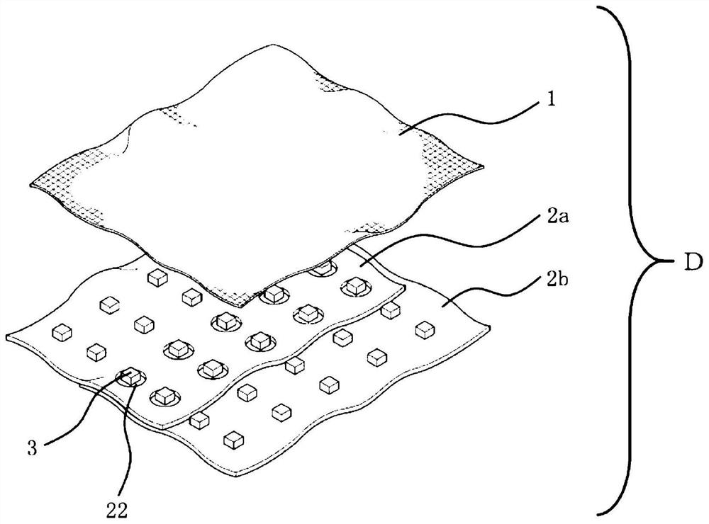
[0043] like image 3 As shown, the display device D as another embodiment of the present invention may be formed by fitting the LED device connecting portion 22 and the LED element 3 to connect th...


PUM

PropertyMeasurementUnit
thicknessaaaaaaaaaa
widthaaaaaaaaaa
thicknessaaaaaaaaaa

Abstract

The purpose of the present invention is to obtain a display device which does not feel the presence of an LED device when the LED device does not emit light, has an excellent display effect when the LED device emits light, and has excellent designability and flexibility. Specifically, the display device includes: an LED device including a plurality of LED elements soldered to one surface side of a flexible substrate; and a porous material covering at least a portion of the LED arrangement surface side of the LED device.

Description

technical field [0001] The present invention relates to a display device including a flexible LED device and a porous material covering at least a part of an LED arrangement surface side of the LED device. Background technique [0002] LED display devices such as dot matrix display devices are rapidly spreading, and the LED display devices can display information such as arbitrary characters, symbols, and patterns by selectively emitting light from LED elements. [0003] Conventional LED display devices have widely used devices in which LED elements are mounted on a substantially inflexible rigid substrate. However, since the degree of freedom of design of such an LED display device is low, its use and the like are limited. [0004] As a flexible LED display device that can be formed into a target shape, for example, the devices listed in Patent Documents 1 and 2 are known. [0005] In Patent Document 1, it is described that it can be wound around a pillar or the like in a...

Claims


Application Information

Patent Timeline
Patent Type & Authority Applications(China)
IPC IPC(8): H01L33/52H01L33/48H01L25/075G09F9/30G09F9/33
CPCH01L33/483H01L33/52H01L25/0753G09F9/33G09F9/301
Inventor 福田光树杉山和弘望月保嗣佐佐木柾之
Owner SAKATA INX
Why Eureka
Try Eureka