A marine power distribution cabinet with a ventilation and dehumidification structure

A technology for ships and power distribution cabinets, which is applied in the substation/power distribution device shell, substation/switchgear cooling/ventilation, electrical components, etc., and can solve the influence of dehumidification operation of ship power distribution cabinets Operation and other issues, to achieve the effect of improving ventilation and dehumidification, improving work stability, and reducing the impact caused by direct airflow

Active Publication Date: 2022-07-01
宝嘉智能科技(南通)有限公司
View PDF5 Cites 6 Cited by
  • Summary
  • Abstract
  • Description
  • Claims
  • Application Information

AI Technical Summary

Problems solved by technology

[0003] In the prior art, since the ship sails on the water for a long time, the degree of humidity in the working environment of the power distribution cabinet on the ship is relatively high. In order to ensure the stability of the circuit components inside the power distribution cabinet, the Hygroscopic components are installed inside to remove the moisture entering the power distribution cabinet in a timely manner. Most of the commonly used hygroscopic components are directly fixed and installed inside the power distribution cabinet. During long-term use, regular maintenance and replacement are required, and it is difficult to continuously distribute power to ships. The dehumidification operation inside the cabinet makes the dehumidification operation inside the ship's power distribution cabinet easily affected

Method used


Image

  • A marine power distribution cabinet with a ventilation and dehumidification structure
  • A marine power distribution cabinet with a ventilation and dehumidification structure
  • A marine power distribution cabinet with a ventilation and dehumidification structure

Examples


Embodiment 1

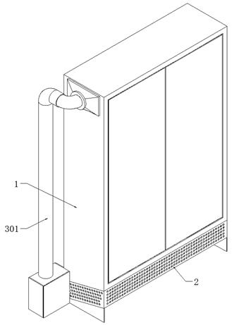
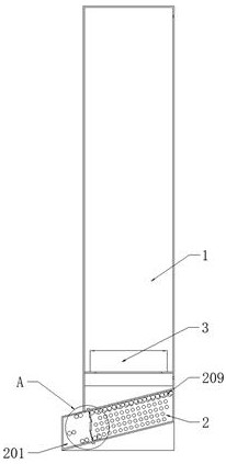
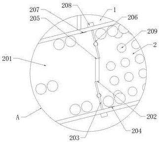
[0046] see Figure 1-10 , a marine power distribution cabinet with a ventilation and dehumidification structure, comprising a cabinet 1, a dehumidification box 2 is fixedly installed at the bottom of the cabinet 1, and a re-drying box 201 is fixedly welded on the back of the dehumidification box 2, and the dehumidification box 2 and the complex A laterally arranged through groove 202 is opened under the end wall of the side where the dry box 201 is attached, and a laterally arranged return groove 205 is opened above the end wall of the side where the dehumidification box 2 and the re-drying box 201 are attached. The interior of the hygroscopic ball 209 is filled with a plurality of hygroscopic balls 209, and the hygroscopic ball 209 includes a hollow ball arranged at the inner middle position, the outer surface of the hollow ball is uniformly adhered with activated carbon, and the interior of the hollow ball is filled with light gas. The interior of the cabinet 1 is fixedly in...


PUM


Abstract

The invention discloses a marine power distribution cabinet with a ventilation and dehumidification structure, belonging to the field of power distribution cabinets. A marine power distribution cabinet with a ventilation and dehumidification structure includes a cabinet, and a dehumidification box is fixedly installed at the bottom of the cabinet. And the back of the dehumidification box is fixedly welded with a re-drying box, which can realize the continuous moisture absorption operation of the airflow entering the cabinet. On the top of the hygroscopic bulb, with the help of the through groove and the return groove opened between the dehumidification box and the re-drying box, the hygroscopic bulb can absorb moisture inside the dehumidification box and dehumidify inside the re-drying box, thus forming a continuous dehumidification mode of circulating flow, It is convenient to perform uninterrupted dehumidification operation on the gas entering the cabinet, which effectively improves the ventilation and dehumidification effect of the device.

Description

technical field [0001] The invention relates to the field of power distribution cabinets, and more particularly, to a marine power distribution cabinet with a ventilation and dehumidification structure. Background technique [0002] The marine power distribution cabinet is a kind of box equipment used to compress the circuit control components on the ship. It can effectively provide protection, control and supervision for the circuit control components, and is an important component in the marine power control system. one. [0003] In the prior art, because the ship sails on the water for a long time, the humidity in the working environment of the power distribution cabinet on the ship is relatively high. In order to ensure the stability of the circuit components inside the power distribution cabinet, the Moisture-absorbing components are installed inside to facilitate timely removal of the moisture entering inside the power distribution cabinet. Most of the commonly used m...

Claims


Application Information

Patent Timeline
Patent Type & Authority Patents(China)
IPC IPC(8): H02B1/28B01D53/26B01D53/28B01D53/96H02B1/56H02B1/32
CPCH02B1/28B01D53/261B01D53/28B01D53/268B01D53/96H02B1/565H02B1/32Y02A30/14
Inventor 杨清
Owner 宝嘉智能科技(南通)有限公司
Why Eureka
Try Eureka