Cutting device for wire and cable processing and cutting method thereof

A cutting device, wire and cable technology, applied in the field of cutting devices for wire and cable processing, can solve the problems of uneven contact surface, increased resistance value, easy scratching of operators, etc., and achieve uniform cutting surface and no out-of-roundness. Effect

Active Publication Date: 2022-06-07
永新县宏展电线电缆有限公司
View PDF5 Cites 1 Cited by
  • Summary
  • Abstract
  • Description
  • Claims
  • Application Information

AI Technical Summary

Problems solved by technology

[0005] The purpose of the present invention is to provide a cutting device for wire and cable processing and a cutting method thereof, so as to solve the problem that in the existing cable cutting process proposed in the above-mentioned background technology, a pliers-shaped cutting tool is used to directly cut the cable. Due to the hands on both sides of the cable, the end surface of the cable after cutting is flat, and there will be a sharp shear surface, which is very easy to scratch the operator during the later construction process, and the flat cut is not conducive to the circular cable The connectors are directly docked, which affects the work progress; secondly, although the existing small circular cutter is small and portable, when cutting thicker cables, due to the unstable fixed point, it often shakes during cutting, making the cutting There is a problem that the tool is stuck, causing the handle to rotate, which is likely to cause injury to the operator. Secondly, the shaking during cutting can easily lead to irregular cut surfaces. In the subsequent connection process, it is easy to cause uneven contact surfaces and increase the resistance value. Causes problems of fusing or starting

Method used


Image

  • Cutting device for wire and cable processing and cutting method thereof
  • Cutting device for wire and cable processing and cutting method thereof
  • Cutting device for wire and cable processing and cutting method thereof

Examples


Embodiment Construction

[0025] The technical solutions in the embodiments of the present invention will be clearly and completely described below with reference to the accompanying drawings in the embodiments of the present invention. Obviously, the described embodiments are only a part of the embodiments of the present invention, but not all of the embodiments. Based on the embodiments of the present invention, all other embodiments obtained by those of ordinary skill in the art without creative efforts shall fall within the protection scope of the present invention.

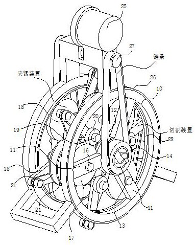
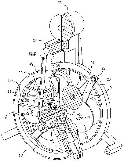
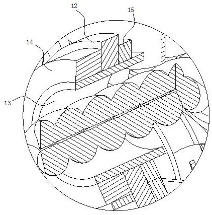
[0026] see Figure 1-6, the present invention provides a technical solution: a cutting device for wire and cable processing, including a clamping device and a cutting device, the clamping device includes a revolving ring plate 10, and the inner wall of the revolving ring plate 10 is fixedly arranged in an annular array around its axis. A plurality of mounting brackets 11, one end of each mounting bracket 11 away from the revolving rin...


PUM


Abstract

The invention discloses a cutting device for wire and cable processing in the technical field of cutting for wire and cable processing, the cutting device comprises a clamping device and a cutting device, the clamping device comprises a revolution ring plate, and a plurality of mounting frames are fixedly arranged between the inner walls of the revolution ring plate around the axis of the revolution ring plate in an annular array mode; a fixed ring plate is fixedly arranged at the end, away from the revolution ring plate, of each mounting frame, and a hollow power bearing shaft is rotationally arranged on the inner wall of each fixed ring plate. A clamping chain wheel is coaxially and fixedly arranged on the outer wall of the power bearing shaft located on the side wall of the fixed annular plate. The cable cutting device solves the problems that in the cable cutting process, a pincerlike cutting tool is used for directly cutting a cable, due to the fact that the two sides of the cable are stressed, the end face of the cut cable is in a flat shape, a sharp shearing face can appear, and operators are extremely prone to being scratched in the later construction process; and the flat notch is not beneficial to direct butt joint of the annular cable connector, so that the working progress is influenced.

Description

technical field [0001] The invention relates to the technical field of cutting for wire and cable processing, in particular to a cutting device for wire and cable processing and a cutting method thereof. Background technique [0002] Cable is a general term for optical cables, cables and other items. There are many uses of cables, mainly used for multiple functions such as control installation, connection equipment, and power transmission. It is a common and indispensable thing in daily life. The manufacturing process of wire and cable and the development of special equipment are closely related and promote each other. The new process requirements promote the generation and development of new special equipment; in turn, the development of new special equipment improves the promotion and application of new processes. Such as wire drawing, annealing, extrusion series line; physical foaming production line and other special equipment, promote the development and improvement o...

Claims


Application Information

Patent Timeline
Patent Type & Authority Applications(China)
IPC IPC(8): B21F11/00
CPCB21F11/00Y02W30/82
Inventor 周红亮李传红
Owner 永新县宏展电线电缆有限公司
Why Eureka
Try Eureka