
Improved control method for low voltage ride through of renewable energy power generation system

A renewable energy, low-voltage ride-through technology, applied to electrical components, circuit devices, AC network circuits, etc., can solve problems such as out-of-step and off-grid, unproposed, unavoidable system out-of-step risks, etc., to improve the stability of large disturbances performance, avoiding the risk of off-grid accidents, and solving the effect of transient out-of-synchronization problems

Pending Publication Date: 2022-06-07
XINJIANG TIANFU ENERGY CO LTD +1
View PDF0 Cites 0 Cited by
  • Summary
  • Abstract
  • Description
  • Claims
  • Application Information

AI Technical Summary

Problems solved by technology

However, this method can only improve the small-signal stability of the system, and cannot avoid the risk of system out-of-synchronization
Literature [2], starting from the electromechanical time scale, studied the large disturbance instability phenomenon of the double-fed wind power generation system during the low-voltage ride-through period of the weak grid, and found that the large-scale disturbance of the double-fed wind power system during the low-voltage ride-through period was out of step and out of the grid Instability phenomenon, but the literature did not propose corresponding improvement control measures

Method used


Image

  • Improved control method for low voltage ride through of renewable energy power generation system
  • Improved control method for low voltage ride through of renewable energy power generation system
  • Improved control method for low voltage ride through of renewable energy power generation system

Examples


Embodiment Construction

[0025] The specific embodiments of the present invention will be described in detail below with reference to the accompanying drawings.

[0026] The improved control method of the renewable energy power generation system during the low voltage ride-through period provided by the present invention is used to improve the large disturbance stability of the renewable energy power generation system during the low voltage ride through period. The method relates to the processing of the input signal of the phase-locked loop three-phase voltage signal of the renewable energy power generation system.

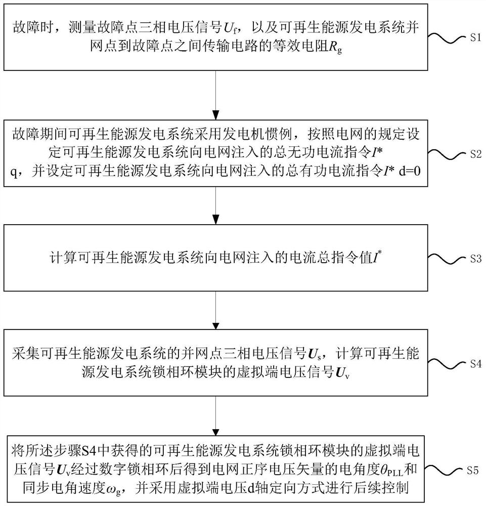
[0027] like figure 1 The specific steps shown include the following:

[0028] S1: When there is a fault, measure the three-phase voltage signal U at the fault point f , and the equivalent resistance R of the transmission circuit between the grid connection point and the fault point of the renewable energy power generation system g ;

[0029] S2: During the fault period, the renewable...


PUM


Abstract

The invention discloses an improved control method for low voltage ride through of a renewable energy power generation system. The method specifically comprises the following steps: measuring a three-phase voltage signal of a fault point and equivalent resistance of a transmission circuit between a grid-connected point of the renewable energy power generation system and the fault point; calculating a total instruction value I * of current injected into the power grid by the renewable energy power generation system; the method comprises the following steps: collecting a grid-connected point three-phase voltage signal Us of a renewable energy power generation system, and calculating a virtual terminal voltage signal Uv of a phase-locked loop module of the renewable energy power generation system; a virtual end voltage signal Uv of a phase-locked loop module of the renewable energy power generation system passes through a digital phase-locked loop to obtain an electrical angle theta PLL and a synchronous electrical angular velocity omega g of a positive sequence voltage vector of a power grid, and subsequent control is carried out by adopting a virtual end voltage d-axis orientation mode. According to the invention, through processing and improving control of the phase-locked loop three-phase voltage signal input signal of the renewable energy power generation system, the problem of large interference instability of the renewable energy power generation system during the low voltage ride-through period is avoided.

Description

technical field [0001] The invention relates to the field of new energy power generation, in particular to an improved control method of a renewable energy power generation system during low voltage ride through. Background technique [0002] At present, the conventional wind power / photovoltaic and other renewable energy power generation systems mostly use the phase-locked synchronous control mode based on the phase-locked loop, and its operating characteristics are heavily dependent on the operating state of the power grid. However, with the large-scale and centralized development of renewable energy sources such as wind power / photovoltaic, as well as cross-regional and long-distance transmission, the connection between the renewable energy power generation system and the main grid is tending to weaken. The interaction between the output power flow of the renewable energy power generation system and the grid impedance is becoming more and more obvious, especially during the...

Claims


Application Information

Patent Timeline
Patent Type & Authority Applications(China)
IPC IPC(8): H02J3/38H02J3/44H02J3/46H02J3/24
CPCH02J3/38H02J3/44H02J3/466H02J3/241H02J2300/24Y02E40/30
Inventor 朱锐黎劲松杨宝起韩连山王新宝高玉喜刘子俊陈建东杨成刘洋
Owner XINJIANG TIANFU ENERGY CO LTD
Learn More