Liquid taking device for obstetrics and gynecology department

A kind of obstetrics and gynecology, frame technology, applied in the field of obstetrics and gynecology liquid collection device, can solve the problems of limited liquid collection, patient pain, high psychological pressure, etc., and achieve the effect of avoiding psychological burden and improving environmental hygiene

Inactive Publication Date: 2022-06-17
上海国为医疗科技有限公司
View PDF0 Cites 0 Cited by
  • Summary
  • Abstract
  • Description
  • Claims
  • Application Information

AI Technical Summary

Problems solved by technology

[0002] In the pathological examination of patients in obstetrics and gynecology, it is necessary to obtain the secretion of the patient's female genitalia for etiological analysis. The existing fluid collection work is mostly carried out by inserting the doctor's hand-held cotton swab into the patient's female genitalia for fluid collection. , the effect of this way of taking liquid is poor and the amount of liquid taken is limited, and when the patient's female genital opening still maintains the vaginal valve, in order to avoid damage to the vaginal valve, the doctor needs to observe the patient's female genitalia at close range during the liquid collection work, resulting in The psychological pressure of the patient is relatively high, and there is a high probability of causing pain to the patient due to the cotton swab touching the vaginal flap. There is also a lack of corresponding devices in the prior art to solve the above problems

Method used


Image

  • Liquid taking device for obstetrics and gynecology department
  • Liquid taking device for obstetrics and gynecology department
  • Liquid taking device for obstetrics and gynecology department

Examples


Embodiment Construction

[0037]The technical solutions in the embodiments of the present invention will be clearly and completely described below with reference to the accompanying drawings in the embodiments of the present invention. Obviously, the described embodiments are only a part of the embodiments of the present invention, rather than all the embodiments. Based on the embodiments of the present invention, all other embodiments obtained by those of ordinary skill in the art without creative efforts shall fall within the protection scope of the present invention.

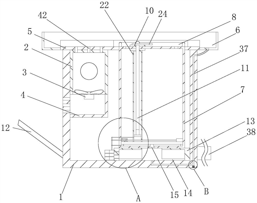
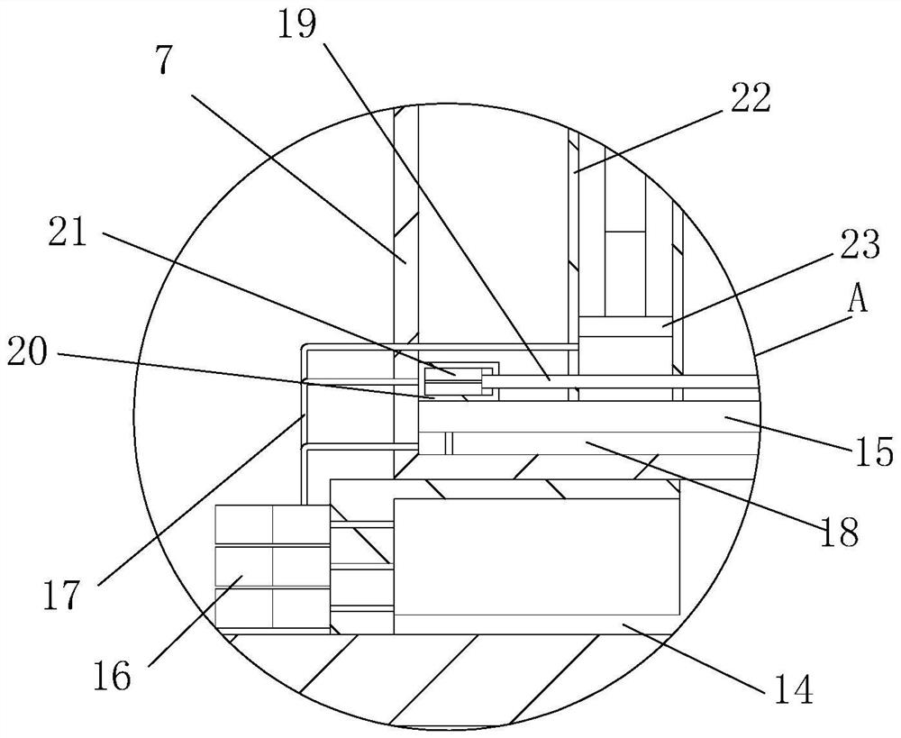
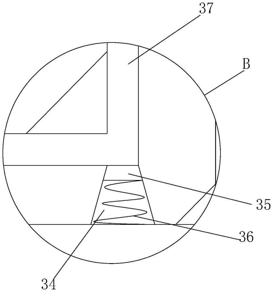
[0038] see Figure 1-8 , an obstetrics and gynecology liquid taking device, comprising a frame body 1 in a hollow state and a sticker 5 arranged on the top surface of the frame body 1, the top surface of the right side of the frame body 1 is provided with a round hole and sleeved with a sticker tube 7, The top surface of the sticking cylinder 7 is provided with a sliding hole 9, a splint 10 with an I-shaped cross section is sleeved in...


PUM


Abstract

The invention relates to the technical field of gynaecology and obstetrics, and discloses a gynaecology and obstetrics liquid taking device which comprises a frame body and a pasting plate arranged on the top face of the frame body, a round hole is formed in the top face of the right side of the frame body, a pasting cylinder is sleeved with the round hole, a sliding hole is formed in the top face of the pasting cylinder, a clamping plate is sleeved with the sliding hole, a hole is formed in the center of the clamping plate, and a liquid taking label is sleeved with the hole. A force arm rod with a hole formed in the top face of the left side fixedly sleeves the outer wall of the liquid taking label, a groove is formed in the top face of the clamping plate, a rotating bearing with an inner ring fixedly connected with the force arm rod is fixedly installed in the groove, a camera is fixedly installed on the top face of the force arm rod, and a display device electrically connected with the camera is fixedly installed on the left side face of the frame. When a doctor takes liquid from a patient with a vaginal valve, the doctor is assisted to accurately correspond the liquid taking label to an opening of the vaginal valve by adjusting the position of the liquid taking label and displaying the female genital organ of the patient, and the probability that the patient is injured and suffers from severe pain due to the fact that the liquid taking label touches the vaginal valve during liquid taking is greatly reduced.

Description

technical field [0001] The invention relates to the technical field of obstetrics and gynecology, in particular to a liquid collection device for obstetrics and gynecology. Background technique [0002] In the pathological diagnosis of patients in the obstetrics and gynecology department, it is necessary to obtain the secretion fluid in the female genitalia of the patient for analysis of the cause. The existing liquid extraction work is mostly carried out by the doctor holding a cotton swab and inserting the patient's female genitalia to extract the fluid. The effect of taking liquid in this way is poor and the amount of liquid taking is limited, and when the patient's female genital orifice still maintains the vaginal valve, in order to avoid damage to the vaginal valve, the doctor needs to observe the patient's female genitalia at close range during the liquid-taking work, resulting in The psychological pressure of the patient is relatively large, and there is a high proba...

Claims


Application Information

Patent Timeline
IPC IPC(8): A61B10/00A61F7/00A61M31/00
CPCA61B10/0045A61M31/00A61F7/0053A61F7/0085A61B2010/0074A61M2210/1475A61F2007/005A61F2007/006A61M2210/005
Inventor 袁辉周耀文
Owner 上海国为医疗科技有限公司
Why Eureka
Try Eureka