Atomization device and atomization equipment

A technology of atomization device and atomization components, which is applied in the field of tobacco, etc., can solve the problems of many parts, high labor and material costs, and achieve the effects of fewer parts, enhanced connection stability, saving material costs and labor installation costs

Pending Publication Date: 2022-06-24
SHENZHEN SKE TECH CO LTD
0 Cites 0 Cited by

AI-Extracted Technical Summary

Problems solved by technology

Resulting in more and smaller part...

Method used

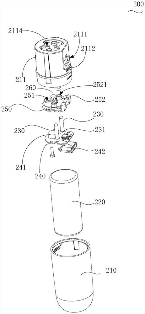
Further, as shown in FIG. 3 , the power supply device 200 also includes a cover member 250, the airflow sensor 241 and the conductive electrode 230 are installed on the same side of the control circuit board 240, and the charging plug The terminals 242 and other electronic components are arranged on the other side of the control circuit board 240 . The cover member 250 covers the airflow sensor 241 , and defines a window 251 corresponding to the triggering area of ​​the airflow sensor 241 , and defines an escape hole 2521 corresponding to the conductive electrode 230 . The side of the cover member 250 facing away from the control circuit board 240 is attached to the inner wall of the main body 210 so that a sealed air path is formed between the window 251 and the triggering air flow, thereby improving the triggering accuracy.
Further, as shown in FIG. 6 in conjunction with FIG. 9, in the embodiment of the present application, in order to prevent the atomizing device 100 from being disassembled from the power supply device 200, the conductive electrode 230 is pulled out from the electrode hole 31 while the sealing seat 30 A phenomenon in which the entrainment causes detachment from the casing 10 occurs. In this embodiment, the atomizing device 100 further includes a support seat 60 , the side peripheral wall of the support seat 60 is clamped in the housing 10 with interference, and is located on the side of the sealing seat 30 facing the opening 12 . The way of clamping can be the way that the entire side peripheral wall is tightly fitted by interference, and a plurality of interference protrusions 64 can also be protruded from the outer peripheral surface of the support seat 60, and the interference protrusions 64 can be arranged along the periphery of the support seat 60. They are arranged at intervals in the direction, and the intervals form disassembly slots 641 for insertion of external disassembly jigs. The outer wall of the interference protrusion 64 and the inner wall of the housing 10 are interferingly clamped. In this application, the interference bump 64 is used to connect with the housing 10, so as to facilitate the disassembly of the atomization device 100, and avoid the phenomenon that it can only be disassembled violently after a processing error. At the same time, the support seat 60 is provided with gaps 61 corresponding to the air inlet 32 ​​and the electrode hole 31, so as not to affect the insertion of the air intake and the conductive electrode 230 into the electrode hole 31. When the conductive electrode 230 is pulled out, the support seat 60 has a limiting and supporting effect on the sealing seat 30, thereby effectively preventing the phenomenon that the sealing seat 30 is detached.
Further, as shown in Figure 3, the control circuit board 240 is also electrically integrated with an airflow sensor 241, and the plug joint 211 of the main body 210 is provided with a trigger air hole 2114, when the insertion head is inserted into the atomizer When the device 100 is inserted into the cavity 40 , the trigger air hole 2114 communicates with the air inlet 32 ​​and the area where the airflow sensor 241 is located. The airflow sensor 241 uses a negative pressure sensor. When the user sucks, the airflow in the area where the airflow sensor 241 is located flows into the air inlet 32 ​​through the trigger air hole 2114 to form a negative pressure, thus triggering the airflow sensor 241. The control circuit The board 240 receives the signal that the airflow sensor 241 is triggered, and drives the internal battery 220 to output through the conductive electrode 230, thereby effectively avoiding the false triggering caused by setting the physical button on the main body 210.
Further, as shown in Figure 4, the cover member 250 is also convexly provided with a reinforcing tube 252 around the avoidance hole 2521, and the hollow area of ​​the reinforcing tube 252 is passed by the conductive electrode 230, so when the conductive When the electrode 230 is subjected to an external force, the reinforcing tube 252 has a supporting effect on the conductive electrode 230 , so as to prevent the conductive electrode 230 from being desoldered from the control circuit board 240 under the external force. The inner wall of the main body 210 is provided with an inserting hole corresponding to the reinforcing tube 252, and the reinforcing tube 252 is inserted into the inserting hole, so as to realize positioning installation.
Specifically, as shown in FIG. 4, one end of the conductive electrode 230 is embedded in or passes through the control circuit board 240, and is welded with the control circuit board 240 to establish an electrical connection, without additionally setting a connecting wire , Reduce the wire welding process. The control circuit board 240 is arranged vertically to the conductive electrode 230, and is locked inside the main body 210 by a locking member such as a screw, so as to provide support for the conductive electrode 230 and prevent the conductive electrode 230 from becoming loose when repeatedly plugging and unplugging.
Specifically, as shown in Fig. 7 to Fig. 9, described support seat 60 is provided with inserting groove 62, and described seal seat 30 is provided with inserting boss 35, and described inserting groove 62 is provided with There is the gap 61, the insertion boss 35 is provided with an air inlet hole and the electrode hole 31; the insertion boss 35 is inserted into the insertion groove 62 with elastic interference, so that the The bottom groove wall of the insertion groove 62 presses the conductive pin 52 into the blind wire-passing groove 312 . In this way, the phenomenon that the conductive pin 52 is squeezed and pulled by the conductive electrode 230 and the atomizing core 51 inside the atomization assembly 50 is pulled along with the conductive pin 52 is further avoided. And cover the conductive pins 52 to make the product more beautiful.
Specifically, as shown in Figure 1 and Figure 4, the end of the main body 210 away from the insertion head is also provided with an ultraviolet germicidal lamp 270, and the ultraviolet germicidal lamp 270 is electrically connected to the control circuit board 240 . When the external charging cable is plugged into the charging plug terminal 242 along the charging port 2111, the control circuit board 240 drives the ultraviolet germicidal lamp 270 to work, thereby emitting ultraviolet rays toward the insertion cavity 40 of the atomizing device 100 to achieve sterilization during charging. Effect.
Specifically, in order to prevent the solution in the liquid storage chamber 20 from directly leaking from the atomization gas path inside the atomization assembly 50, and prevent the solution from being injected into the next station when the solution is injected, the solution in the liquid storage chamber 20 will leak out phenomenon occurs. As shown in Figure 6, in the embodiment of the present application, the liquid storage chamber 20 is filled with a liquid-absorbent substrate 21, and the liquid-absorbent substrate 21 can be made of organic cotton, polyester fiber, etc., which is not limited here . This application selects the polyester fiber with relatively fixed shape. thereby facilitating installation.
[0043] Specifically, in order to facilitate installation, prevent the support seat 60 from being installed in the housing 10 to apply excessive pressure, resulting in the deformation of the atomization assembly 50 or the sealing seat 30. As shown in Figure 6 and Figure 7, in the embodiment of the present application, the inner wall ...

Abstract

The invention provides an atomization device and atomization equipment. The atomization device comprises a shell, one end of which is provided with a suction port and the other end of which is open; the atomization assembly is constructed in the shell, and an atomization gas path in the atomization assembly communicates with the suction opening; the flexible sealing seat blocks the opening and provides support for the atomization assembly, the sealing seat is provided with an air inlet and an electrode hole exposed to the outside, the air inlet is communicated with the outside and the atomization air path, and a conductive pin of the atomization assembly extends into the electrode hole. The invention aims to reduce the production cost of products.

Application Domain

Tobacco

Technology Topic

Electrically conductiveEngineering +3

Image

  • Atomization device and atomization equipment
  • Atomization device and atomization equipment
  • Atomization device and atomization equipment

Examples

  • Experimental program(1)

Example Embodiment

[0035] In order to make the technical problems, technical solutions and beneficial effects to be solved by the present application clearer, the present application will be described in further detail below with reference to the accompanying drawings and embodiments. It should be understood that the specific embodiments described herein are only used to explain the present application, but not to limit the present application.
[0036] It should be noted that when an element is referred to as being "fixed to" or "disposed on" another element, it can be directly on the other element or indirectly on the other element. When an element is referred to as being "connected to" another element, it can be directly connected to the other element or indirectly connected to the other element.
[0037] It is to be understood that the terms "length", "width", "upper", "lower", "front", "rear", "left", "right", "vertical", "horizontal", "top" , "bottom", "inside", "outside", etc. indicate the orientation or positional relationship based on the orientation or positional relationship shown in the accompanying drawings, only for the convenience of describing the application and simplifying the description, rather than indicating or implying the indicated A device or element must have a particular orientation, be constructed and operate in a particular orientation and therefore should not be construed as a limitation of the present application.
[0038] In addition, the terms "first" and "second" are only used for descriptive purposes, and should not be construed as indicating or implying relative importance or implying the number of indicated technical features. Thus, a feature defined as "first", "second" may expressly or implicitly include one or more of that feature. In the description of the present application, "plurality" means two or more, unless otherwise expressly and specifically defined.
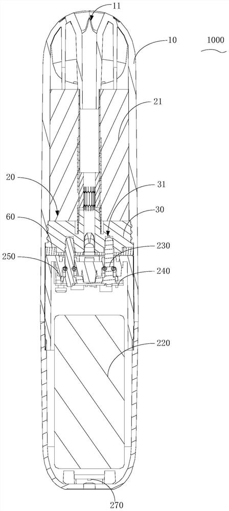
[0039] see Figure 1 to Figure 9 , the embodiment of the present application provides an atomizing device 100, which is applied to the atomizing device 1000. The atomizing device 1000 includes a power supply device 200, and the power supply device 200 is provided with a cyclically rechargeable battery 220 and a battery 220 connected to the battery. 220 is electrically connected to a conductive electrode 230, the conductive electrode 230 is used to output current to the outside; the atomizing device 100 includes a casing 10, an atomizing assembly 50 and a flexible sealing seat 30, one end of the casing 10 is provided with a pump. The other end of the suction port 11 is provided in the shape of an open opening 12 . The flexible sealing seat 30 is made of materials with certain elastic properties such as silica gel and rubber. In the embodiment of the present application, silica gel material is selected. The sealing seat 30 is installed in the housing 10 and blocks the opening. 12. The outer peripheral surface of the sealing seat 30 is sealed with an interference fit with the inner peripheral surface of the casing 10 , so that a sealed liquid storage chamber 20 is formed inside the casing 10 ; the liquid storage chamber 20 stores the solution to be atomized. The atomizing assembly 50 is built in the casing 10 , and one end of the atomizing assembly 50 is communicated with the suction port 11 , and the other end is mounted on the support base 60 , and is supported and positioned in the casing 10 by the support base 60 . The liquid storage chamber 20. The atomizing gas path and the atomizing core 51 are arranged inside the atomizing assembly 50, and the outer wall is provided with a liquid inlet connecting the liquid storage chamber 20 and the inside of the atomizing assembly 50, and the solution to be atomized can pass through the The liquid inlet hole flows to the atomizing core 51 , one end of the atomizing gas path is communicated with the suction port 11 , and the other end is communicated with the outside through the air inlet 32 ​​provided on the sealing seat 30 . When the user sucks, the atomizing core 51 generates heat under the driving of the current, so as to heat and atomize the solution to be atomized into an aerosol and discharge it through the suction port 11 for the user to suck. The solution to be atomized may be a medicinal liquid rich in medicinal components or a nicotine-containing cigarette liquid, so that the atomizing device 1000 can form a medical atomizer and an electronic cigarette.
[0040] Further, as Figure 7 , combined Figure 8 As shown, in the embodiment of the present application, the sealing seat 30 is provided with electrode holes 31 , the conductive pins 52 of the atomizing component 50 extend into the electrode holes 31 , and the number of the electrode holes 31 is two Each of the two conductive pins 52 of the atomizing assembly 50 extends into the two electrode holes 31 respectively. When the atomizing device 100 is installed on the power supply device 200, the two conductive electrodes 230 of the power supply device 200 are inserted into the electrode holes 31, so that the battery 220 inside the power supply device 200 and the atomizing assembly 50 are electrically connected. connect.
[0041] In the present application, a flexible sealing seat 30 is used to seal the opening 12 of the housing 10 , and the flexible sealing seat 30 is provided with an electrode hole 31 , and then the conductive pin 52 of the atomizing assembly 50 is extended to the electrode hole 31 . When the atomizing device 100 is installed on the power supply device 200 , the conductive electrodes 230 of the power supply device 200 can be inserted into the electrode holes 31 by elastic interference, so that the atomizing device 100 does not need to be additionally provided with a copper conductive member. In addition, since the sealing seat 30 is made of flexible material, under the action of the elastic covering force of the sealing seat 30, the conductive electrodes 230 are in close contact with the conductive pins 52, and the conductive electrodes 230 of the power supply device 200 can be made of one-piece hard metal parts, which do not need to be used. It can be used for spring needles, and there is no need for additional magnets to enhance the stability of the connection. The application has fewer parts, which effectively saves material costs and labor installation costs.
[0042] Further, as Image 6 combine Figure 9 As shown, in the embodiment of the present application, in order to prevent the conductive electrode 230 from being pulled out from the electrode hole 31 when the atomizing device 100 is disassembled from the power supply device 200 , the sealing seat 30 is driven to be separated from the casing 10 at the same time. In this embodiment, the atomizing device 100 further includes a support seat 60 , the side peripheral wall of the support seat 60 is clamped in the casing 10 by interference, and is located on the side of the sealing seat 30 facing the opening 12 , and the interference The way of clamping can be that the entire side peripheral wall is interference-fitted, or the outer peripheral surface of the support seat 60 is further protruded with a plurality of interference bumps 64 , and the interference bumps 64 are along the circumference of the outer circumference of the support seat 60 . They are arranged at intervals in the direction, and the space at the interval forms a dismounting groove 641 into which an external dismounting jig is inserted. The outer wall of the interference protrusion 64 and the inner wall of the housing 10 are clamped by interference. In the present application, the interference bumps 64 are used to connect with the housing 10, so as to facilitate the disassembly of the atomizing device 100, and avoid the phenomenon that only violent disassembly occurs after processing errors. At the same time, the support seat 60 is provided with a gap 61 corresponding to the air inlet 32 ​​and the electrode hole 31, so that the insertion of the air inlet and the conductive electrode 230 into the electrode hole 31 is not affected. When the conductive electrode 230 is pulled out, the support seat 60 has a limiting and supporting effect on the sealing seat 30, so as to effectively prevent the phenomenon that the sealing seat 30 is detached.
[0043] Specifically, in order to facilitate installation, the phenomenon that the support base 60 is installed in the housing 10 is prevented from exerting excessive pressure, resulting in the deformation of the atomizing assembly 50 or the sealing base 30 . like Image 6 , Figure 7 As shown, in the embodiment of the present application, the inner wall of the casing 10 is protruded with a limiting step 15, and specifically, the inner space of the casing 10 includes a wide-diameter section and a narrow-diameter section, and the wide-diameter section faces the opening 12. Setting, the inner wall of the narrow-diameter section forms the liquid storage chamber 20, the limit step 15 is formed at the intersection of the wide-diameter section and the narrow-diameter section, and the wide-diameter section is formed for the support The mounting cavity in which the seat 60 is installed. The support base 60 is pressed into the housing 10 and abuts with the limiting step 15 to limit the position, thereby realizing precise installation.
[0044] Specifically, in order to ensure that the gap 61 provided on the support base 60 is precisely aligned with the air inlet 32 ​​and the electrode hole 31 . like Image 6 , combined Figure 8 , Figure 9 As shown, in the embodiment of the present application, the inner surface of the support seat 60 facing away from the opening 12 is further protruded with two positioning posts 65 , and the sealing seat 30 is correspondingly provided with two positioning holes 37 and two positioning posts 65 The two positioning holes 37 are inserted into the two positioning holes 37 by interference, so that the support base 60 is accurately installed on the sealing base 30 and ensures that the gap 61 provided on the support base 60 is aligned with the air inlet 32 ​​and the electrode hole 31 . And because the sealing seat 30 is made of a flexible material, when the two positioning posts 65 are inserted into the two positioning holes 37 , they are firmly covered by the tension of the sealing seat 30 . When the conductive electrode 230 is inserted into the sealing seat 30 , the damping force between the two positioning posts 65 and the positioning hole 37 can effectively prevent the sealing seat 30 from being displaced toward the liquid storage chamber 20 by the insertion force of the conductive electrode 230 .
[0045] Further, in order to prevent the phenomenon that the sealing seat 30 is deformed toward the liquid storage chamber 20 by the insertion force when the conductive electrode 230 is inserted into the electrode hole 31 provided in the sealing seat 30 . like Figure 7 As shown, in the embodiment of the present application, the outer periphery of the sealing seat 30 is further provided with a sealing edge 33, one end of the sealing seat 30 is inserted into the narrow diameter section of the housing 10 along the opening 12, and is connected with the The inner wall of the narrow-diameter section is sealed with interference; the sealing edge 33 is located in the large-diameter section and abuts against the step surface of the limiting step 15 , and the edge of the support seat 60 presses the sealing edge 33 Close to the step surface of the limiting step 15 . Therefore, by pressing the sealing edge 33 protruding from the outer periphery of the sealing seat 30 against the step surface, and then fixing the sealing seat 30, when the conductive electrode 230 is inserted into the electrode hole 31, the sealing seat 30 will not be blocked by the conductive electrode. The 230 drives the offset, and by providing the sealing edge 33, the sealing effect can be further improved, and the phenomenon that the solution to be atomized stored in the liquid storage chamber 20 is prevented from leaking therefrom occurs.
[0046] It can be understood that, in other embodiments of the present application, it is not limited to the above-mentioned embodiment, in which a whole ring of the sealing edge 33 is protruded on the outer periphery of the sealing seat 30 and is pressed and held by the supporting seat 60 on the limiting step 15 , For example, in other embodiments of the present application, limiting bumps may be protruded from the side wall of the sealing edge 33 , the limiting bumps may be pressed against the stepped surface by the support seat 60 , or The inner wall of the housing 10 is provided with two limit steps 15 at intervals, the limit step 15 near the suction port 11 is used to limit the head end of the sealing seat 30 inserted, and the limit step 15 near the opening 12 is used for limit support The seat 60, and the method of improving the damping and sealing effects by protruding sealing ribs on the outer periphery of the sealing seat 30 also falls within the protection scope of the present application.
[0047] Specifically, to ensure that the conductive electrode 230 can be accurately inserted into the electrode hole 31 when the atomizing device 100 is installed on the power supply device 200 . like Figure 7 to Figure 9 As shown, in the embodiment of the present application, the outer peripheral surface of the support base 60 is further protruded with positioning protrusions 63, and the end surface of the opening 12 of the housing 10 is provided with a positioning groove 41, and the positioning groove 41 extends to The narrow diameter section of the limiting step 15 . The outer peripheral surface of the sealing seat 30 is also protruded with a sealing protrusion 36 , and the positioning protrusion 63 and the sealing protrusion 36 of the supporting seat 60 and the sealing seat 30 correspond to the positioning groove 41 . The direction is installed in the housing 10 , and the positioning protrusion 63 presses the sealing protrusion 36 against the groove wall of the extending end of the positioning groove 41 . Here, in this embodiment, the sealing bumps 36 form the limiting bumps in the above-mentioned embodiments, so that it is not necessary to provide a whole ring of the sealing edge 33 to achieve position limiting. Then, the positioning groove 41 is designed to extend to the narrow diameter section, that is, to be located deep in the step surface. Therefore, the sealing protrusion 36 is pressed against the narrow diameter section by the positioning protrusion 63 , and one side surface of the support seat 60 can abut against the stepped surface of the limiting step 15 . Effectively avoid that when the positioning groove 41 is flush with the stepped surface, a part of the edge of the support seat 60 presses the sealing bump 36 to the stepped surface, and the other part does not press the sealing bump 36 to form a gap between the stepped surface, resulting in the installation of the support seat 60 At the same time, if the pressure on one side is relatively large, the other side will be lifted up, and the phenomenon that the interference bump 64 of the lifted part and the inner wall of the housing 10 are in a virtual position occurs.
[0048] Specifically, as Image 6 As shown, the two positioning holes 37 are through holes penetrating the sealing seat 30, and then communicate with the opening 12 and the liquid storage chamber 20 to form a liquid injection channel. During processing and assembly, the atomizing assembly 50 can be installed on the sealing seat 30 to form After the assembly is installed in the housing 10 as a whole, the solution is injected into the liquid storage chamber 20 through one of the two positioning holes 37. When the liquid is injected, the gas in the liquid storage chamber 20 can be discharged through the other positioning hole 37, so as to increase the injection rate. Fluid smoothness. After the solution is injected, the support base 60 is installed, and the positioning posts 65 of the support base 60 are inserted into the positioning holes 37 to seal the liquid storage cavity 20 .
[0049] Specifically, in order to prevent the solution in the liquid storage chamber 20 from leaking directly from the atomization gas path inside the atomization assembly 50, and at the same time to prevent the leakage of the solution in the liquid storage chamber 20 when the solution is injected and transferred to the next station . like Image 6 As shown, in the embodiment of the present application, the liquid storage cavity 20 is filled with a liquid-absorbing substrate 21, and the liquid-absorbing substrate 21 can be made of organic cotton, polyester fiber, or the like, which is not limited herein. In this application, polyester fibers with a relatively fixed shape are selected. Thereby facilitating installation.
[0050] Specifically, in order to prevent the conductive electrodes 230 from being inserted into the electrode holes 31 , the squeezing force generated on the conductive pins 52 causes the atomizing core 51 inside the atomizing assembly 50 to be displaced. like Figure 7 , Figure 8 As shown, in the embodiment of the present application, the electrode hole 31 includes an insertion hole 313 corresponding to the notch 61 and a blind wire slot 312 extending laterally from the opening of the insertion hole 313 . The side of the seat 30 facing the atomizing assembly 50 is also provided with a blind wire hole 311, and the blind wire hole 311 extends to the position adjacent to the blind wire groove 312 to form a thin-walled piercing portion 3111; The conductive pin 52 is inserted along the blind wire hole 311 , pierces the thin-walled piercing portion 3111 and extends along the blind wire slot 312 , and is bent into the insertion hole 313 . Here, the wall thickness of the thin-walled piercing portion 3111 is 0.5 mm-2 mm, and 1 mm is selected in this application. The penetration portion 3111 has a certain covering force on the conductive pins 52, so as to prevent the phenomenon that the solution to be atomized absorbed by the atomizing core 51 leaks along the conductive pins 52, and the covering force has a certain effect on the conductive pins 52. The conductive pins 52 are arranged along the blind wire-passing grooves 312 to form a first section of bending, and are bent and inserted into the insertion holes 313 again to form a second section of bending. By bending both ends, the direction of the force is changed and the contact area with the sealing seat 30 is increased to improve the damping effect. This can further prevent the conductive pins 52 from being squeezed and pulled by the conductive electrodes 230 , resulting in the phenomenon that the atomizing core 51 inside the atomizing assembly 50 is pulled along with the conductive pins 52 .
[0051] Further, in order to facilitate the installation of the atomizing assembly 50 on the sealing seat 30 . like Figure 5 combine Figure 7 As shown, in the embodiment of the present application, a surface of the sealing seat 30 facing away from the port 12 is protruded with a connecting guide post 34 , and the connecting guide post 34 is hollow to form the air inlet 32 ​​, and the passage The wire blind hole 311 is opened by the end face of the connecting guide post 34. When installing, first pierce the thin-walled piercing portion 3111 with the conductive pin 52 along the wire blind hole 311, and then remove the atomization assembly. 50 is sleeved on the outer periphery of the connecting guide post 34 . At this time, the outer peripheral surface of the connecting guide post 34 is deformed toward the inside by force, so the hole diameter of the blind hole 311 can be reduced, so as to cover the guide pin, which facilitates the installation of the atomizing assembly 50 and improves the electrical conductivity. The damping between the pin 52 and the blind slot 312 further prevents the conductive pin 52 from being squeezed and pulled by the conductive electrode 230, causing the inner atomizing core 51 of the atomizing assembly 50 to be pulled along with the conductive pin 52. .
[0052] Specifically, as Figure 7 to Figure 9 As shown, the support base 60 is provided with a plug groove 62, the sealing base 30 is protruded with a plug boss 35, the plug groove 62 is provided with the gap 61, and the plug boss 35 is provided with an air inlet hole and the electrode hole 31; the insertion boss 35 is elastically inserted into the insertion groove 62, so that the bottom groove wall of the insertion groove 62 will The conductive pins 52 are pressed into the blind wire slot 312 . In this way, the phenomenon that the conductive pins 52 are squeezed and pulled by the conductive electrodes 230 can be further avoided, causing the inner atomizing core 51 of the atomizing assembly 50 to be pulled along with the conductive pins 52 . And cover the conductive pins 52 to make the product more beautiful.
[0053] Further, the present application also provides an atomizing device 1000, the atomizing device 1000 includes a power supply device 200 (not shown) and an atomizing device 100. The specific structure of the atomizing device 100 refers to the above-mentioned embodiment. The chemical device 1000 adopts all the technical solutions of all the above-mentioned embodiments, and therefore at least has all the beneficial effects brought about by the technical solutions of the above-mentioned embodiments, which will not be repeated here.
[0054] Specifically, as image 3 As shown, the power supply device 200 includes a main body 210 and two conductive electrodes 230. The main body 210 is provided with a rechargeable battery 220 and a control circuit board 240 electrically connected thereto. The two conductive electrodes 230 One end is built in the main body 210 and is electrically connected to the control circuit board 240 in the main body 210 , and the other end is exposed to the outside through the main body 210 , and is used for inserting the electrodes provided in the atomizing seat in the atomizing device 100 The hole 31 is used to establish an electrical connection between the control circuit board 240 and the atomizing core 51 . Here, the conductive electrode 230 is made of a hard copper column. When inserted into the electrode hole 31 , the inner hole wall of the electrode hole 31 elastically wraps the outer surface of the conductive electrode 230 , so that the conductive electrode 230 and the The conductive pins 52 are in close contact, so there is no need to use bullet-type electrodes, which saves costs. In addition, the conductive electrode 230 and the sealing seat 30 have an interference force, and there is no need for additional magnets to tightly connect the atomizing device 100 and the power supply device 200 .
[0055] Further, as 1 combined figure 2 As shown, in order to prevent the atomizing device 100 and the power supply device 200 from being damaged by a shearing force caused by the uneven force on the side wall, the two conductive electrodes 230 are damaged. The housing 10 can be designed to be longer, the sealing seat 30 and the supporting seat 60 are built in the middle of the housing 10 to divide the inner space of the housing 10 into the liquid storage chamber 20 and the insertion towards the opening 12 cavity 40 ; the electrode hole 31 and the air inlet 32 ​​are exposed in the insertion cavity 40 . The power supply device 200 is provided with the conductive electrode 230 at one end with a smaller outer diameter to form a plug connector 211 , the plug connector 211 is inserted into the insertion cavity 40 , and the outer wall of the plug connector 211 is connected to the plug connector 211 . The inner wall of the cavity 40 is adapted, and when the atomizing device 100 or the power supply device 200 is subjected to staggered shearing force, the outer wall of the plug connector 211 and the inner wall of the insertion cavity 40 abut to limit the position, thereby avoiding the occurrence of a large force on the conductive electrode 230 damage occurs.
[0056] Specifically, as Figure 4 As shown, one end of the conductive electrode 230 is embedded in or passed through the control circuit board 240, and is welded with the control circuit board 240 to establish electrical connection without additional connection wires, thereby reducing the wire welding process. The control circuit board 240 is vertically arranged with the conductive electrodes 230, and is locked inside the main body 210 by a locking member such as a screw, so as to provide support for the conductive electrodes 230 and prevent the conductive electrodes 230 from loosening during repeated plugging and unplugging.
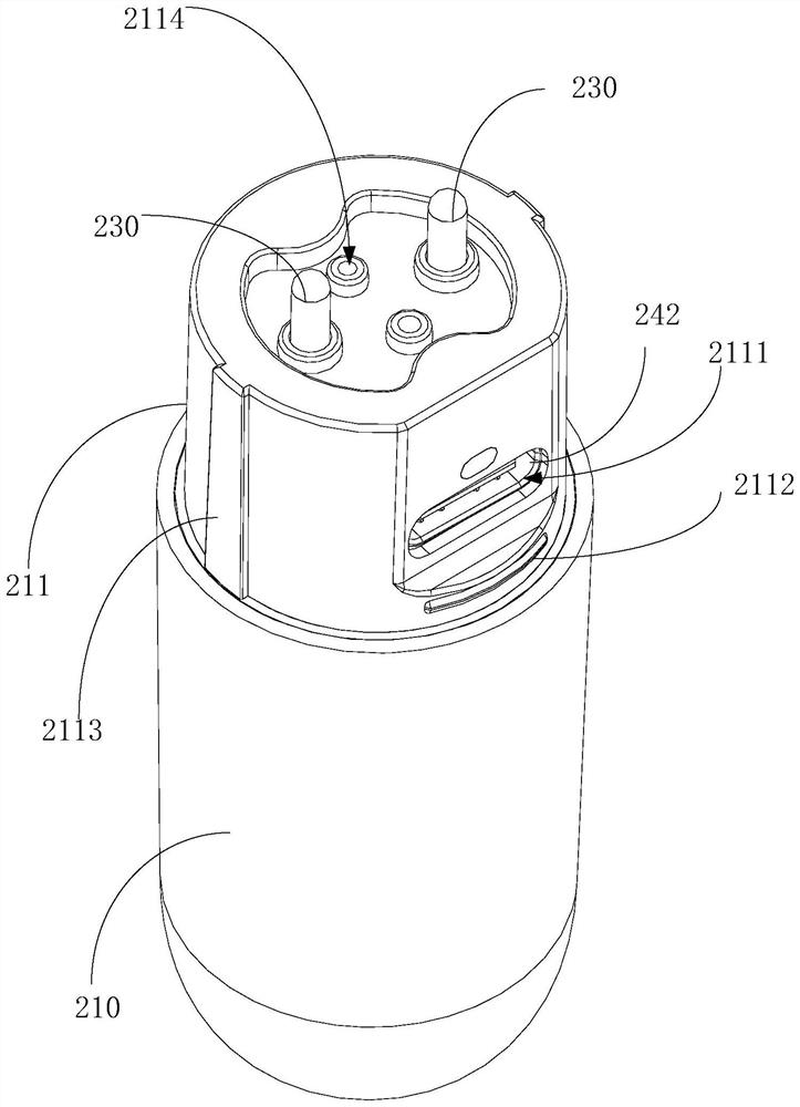
[0057] Specifically, as figure 2 , image 3 As shown, in the embodiment of the present application, the control circuit board 240 is further integrated with a charging plug terminal 242, and a charging port 2111 is also opened on the side wall of the plug connector 211 corresponding to the charging plug terminal 242, so that The external cable can charge the internal battery 220 through the charging port 2111 and the charging plug-in terminal 242 . Here, in the embodiment of the present application, by integrating the charging plug-in terminal 242 into the control circuit board 240 , there is no need to provide an additional charging terminal circuit board, which effectively saves costs. And in the embodiment of the present application, the charging port 2111 is set on the plug connector 211, when the plug connector 211 is inserted into the housing 10 of the atomizing device 100, the charging port 2111 is covered, which effectively enhances the aesthetic performance of the product. . At the same time, when charging is required, the atomizing device 100 needs to be pulled out and then charged, so as to effectively avoid discharging while charging, and the control circuit board 240 is caused by heat concentration when the conductive electrodes 230 and the charging plug terminals 242 work at the same time. Short circuit and other phenomena are easy to occur at high temperature, and independent charging effectively improves the service life of the internal rechargeable battery 220, thereby increasing the service life of the product.
[0058] Further, as image 3 As shown, the control circuit board 240 is also electrically integrated with an airflow sensor 241, and the plug connector 211 of the main body 210 is provided with a trigger air hole 2114. When the insertion head is inserted into the insertion cavity 40 of the atomizing device 100, the The trigger air hole 2114 communicates with the air inlet 32 ​​and the area where the air flow sensor 241 is located. The airflow sensor 241 adopts a negative pressure sensor. When the user sucks, the airflow in the area where the airflow sensor 241 is located flows into the air inlet 32 ​​through the trigger air hole 2114 to form a negative pressure, thus triggering the airflow sensor 241 and the control circuit. The board 240 receives the triggered signal of the airflow sensor 241, and drives the internal battery 220 to output through the conductive electrode 230, thereby effectively avoiding the phenomenon of false triggering caused by physical buttons on the main body 210.
[0059] Further, as image 3 As shown, the power supply device 200 further includes a cover member 250, the airflow sensor 241 and the conductive electrode 230 are mounted on the same side of the control circuit board 240, and the charging plug terminals 242 and other electronic components are arranged on the same side of the control circuit board 240. Control the other side of the circuit board 240 . The cover member 250 covers the airflow sensor 241 , and has a window 251 corresponding to the trigger area of ​​the airflow sensor 241 , and an escape hole 2521 corresponding to the conductive electrode 230 . A side of the cover member 250 away from the control circuit board 240 is attached to the inner wall of the main body 210 to form a sealed air path between the window 251 and the triggering airflow, thereby improving triggering precision.
[0060] Specifically, as Figure 4 As shown, the end of the conductive electrode 230 connected to the control circuit board 240 is further protruded with a limiting edge 231, and the cover member 250 presses the limiting edge 231 against the control circuit board 240 and corresponds to the control circuit board 240. The conductive electrode 230 is also provided with an escape hole 2521 , and the conductive electrode 230 is exposed to the outside through the escape hole 2521 and the main body 210 , so as to further prevent the conductive electrode 230 from being de-soldered from the control circuit board 240 .
[0061] Further, as Figure 4 As shown, the cover member 250 is also protruded with a reinforcing tube 252 around the avoidance hole 2521. The hollow area of ​​the reinforcing tube 252 is for the conductive electrode 230 to pass through. Therefore, when the conductive electrode 230 is subjected to external force, the reinforcing tube 252 The conductive electrodes 230 are supported, so as to prevent the conductive electrodes 230 from being de-soldered from the control circuit board 240 under the action of external force. The inner wall of the main body 210 is provided with an insertion hole corresponding to the reinforcing tube 252 , and the reinforcing tube 252 is inserted into the insertion hole so as to realize positioning and installation.
[0062] Further, as Figure 4 As shown, the outer wall of the conductive electrode 230 or the reinforcing tube 252 is also sleeved with a sealing ring 260, and the sealing ring 260 is sealed with the inner hole wall of the insertion hole, thereby effectively avoiding the waste liquid from the outside. The gap between the extended conductive electrode 230 and the main body 210 penetrates into the main body 210 , causing damage to the electronic components in the main body 210 .
[0063] Specifically, as figure 2 combine Figure 7 As shown, one of the side wall of the plug connector 211 and the inner wall of the housing 10 is further provided with a snap-fit ​​protrusion 2112, and the other of the two is provided with a snap-fit ​​groove 42, and the plug connector 211 is inserted into the When the housing 10 of the atomizing device 100 is installed, the snap-fit ​​protrusion 2112 is snapped into the snap-fit ​​groove, thereby enhancing the stability of the connection and preventing the phenomenon that the atomizer device 100 is easily detached from the power supply device 200 . Since the plug portion is exposed to the outside world, if the snap groove 42 is provided, dust is likely to remain. In the embodiment of the present application, the side wall of the plug connector 211 is provided with a buckling protrusion 2112 protruding, and the inner wall of the housing 10 is provided with a buckling groove 42 .
[0064] Specifically, as figure 2 As shown, the side wall of the plug connector 211 is provided with a positioning rib 2113 corresponding to the positioning groove 41 , so that the plug connector 211 is inserted into the fog in the direction in which the positioning ribs 2113 correspond to the positioning groove 41 . into the insertion cavity 40 of the chemical device 100 . Make sure that the conductive electrode 230 is accurately inserted into the electrode hole 31 .
[0065] Specifically, as image 3 As shown, one end of the main body 210 away from the insertion head is provided in a tapered manner, so that after the atomizing device 100 is pulled out, it can be sleeved on the other end of the main body 210 away from the insertion head.
[0066] Specifically, as figure 1 , Figure 4 As shown, an end of the main body 210 away from the insertion head is further provided with an ultraviolet germicidal lamp 270 , and the ultraviolet germicidal lamp 270 is electrically connected to the control circuit board 240 . When the external charging cable is plugged into the charging plug-in terminal 242 along the charging port 2111, the control circuit board 240 drives the ultraviolet germicidal lamp 270 to work, thereby emitting ultraviolet rays toward the insertion cavity 40 of the atomizing device 100 to achieve sterilization during charging Effect.
[0067] The above descriptions are only preferred embodiments of the present application, and are not intended to limit the present application. Any modifications, equivalent replacements and improvements made within the spirit and principles of the present application shall be included in the protection of the present application. within the range.

PUM

no PUM

Description & Claims & Application Information

We can also present the details of the Description, Claims and Application information to help users get a comprehensive understanding of the technical details of the patent, such as background art, summary of invention, brief description of drawings, description of embodiments, and other original content. On the other hand, users can also determine the specific scope of protection of the technology through the list of claims; as well as understand the changes in the life cycle of the technology with the presentation of the patent timeline. Login to view more.

Similar technology patents

Axle half-shaft structure

Owner:涡阳阿科索机械有限公司

Cheongsam connecting buckle for interval adjusting

Owner:苏州凤霓绣叶文化艺术有限公司

Rotary abutting type screen printing plate

Owner:JIANGSU SHENGXI ELECTRONICS SCI & TECH

Solar cell encapsulation adhesive film

InactiveCN109468076AImprove connection stabilityImprove photostability
Owner:CHANGZHOU SVECK PHOTOVOLTAIC NEW MATERIAL

Classification and recommendation of technical efficacy words

  • Improve connection stability
  • few parts

Expansion-type rotatable tail pipe hanger

ActiveCN102953698ASimple structurefew parts
Owner:CHINA PETROLEUM & CHEM CORP +1

Mobile terminal

InactiveCN103533491Afew partsReduce material and assembly costs
Owner:NUBIA TECHNOLOGY CO LTD

Locking mechanism with self-return function

ActiveCN104727669ASimple structurefew parts
Owner:DEERFU VEHICLE LOCK ANTI THEFT SYST SHANGHAI
Why Eureka
Try Eureka