Multifunctional vacuum dispensing device

A glue dispensing device and multi-functional technology, applied in the field of multi-functional vacuum glue dispensing device, can solve the problems such as difficulty in using electronic weighing equipment, and achieve the effects of preventing impact, improving sealing and prolonging service life.

Active Publication Date: 2022-07-01
SUZHOU TERUITE ROBOT CO LTD
View PDF12 Cites 0 Cited by
  • Summary
  • Abstract
  • Description
  • Claims
  • Application Information

AI Technical Summary

Problems solved by technology

[0004] The purpose of the present invention is to provide a multifunctional vacuum dispensing device, which realizes the weight measurement of liquids in a vacuum environment, and solves the problem that the electronic weighing equipment in the vacuum chamber is difficult to use

Method used


Image

  • Multifunctional vacuum dispensing device
  • Multifunctional vacuum dispensing device
  • Multifunctional vacuum dispensing device

Examples


Embodiment 1

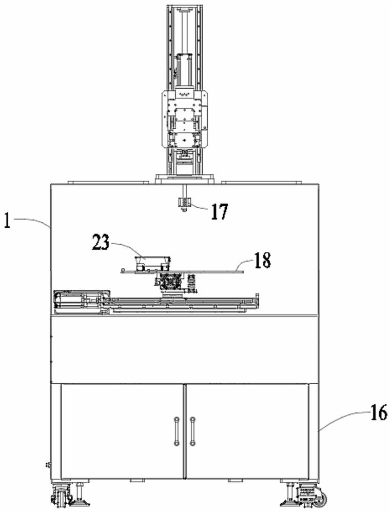
[0033] Example 1: A multifunctional vacuum dispensing device, comprising a sealing chamber 1, a frame 16, a dispensing valve 17 and a workbench 18, the sealing chamber 1 is installed on the frame 16, the dispensing valve 17 and The workbenches 18 are all located in the sealing chamber 1, and the dispensing valve 17 is located directly above the workbenches 18;

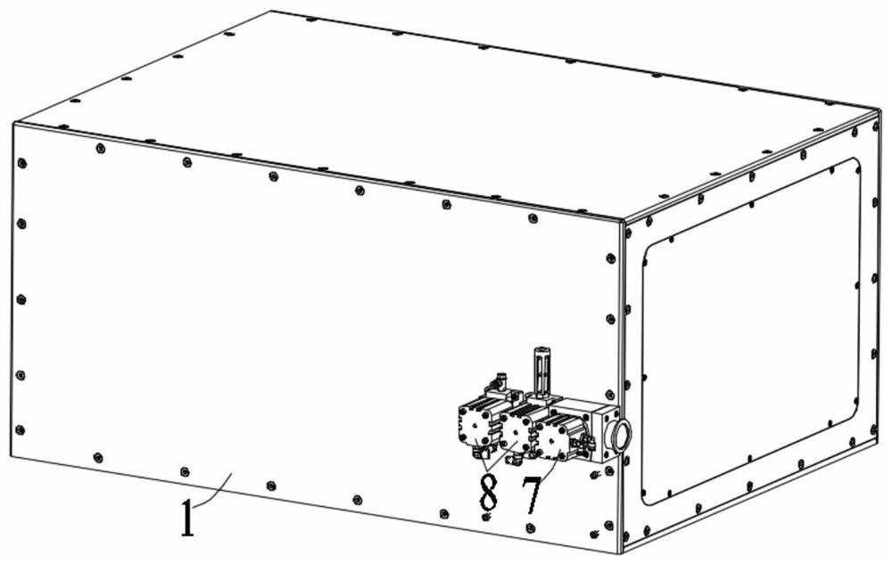
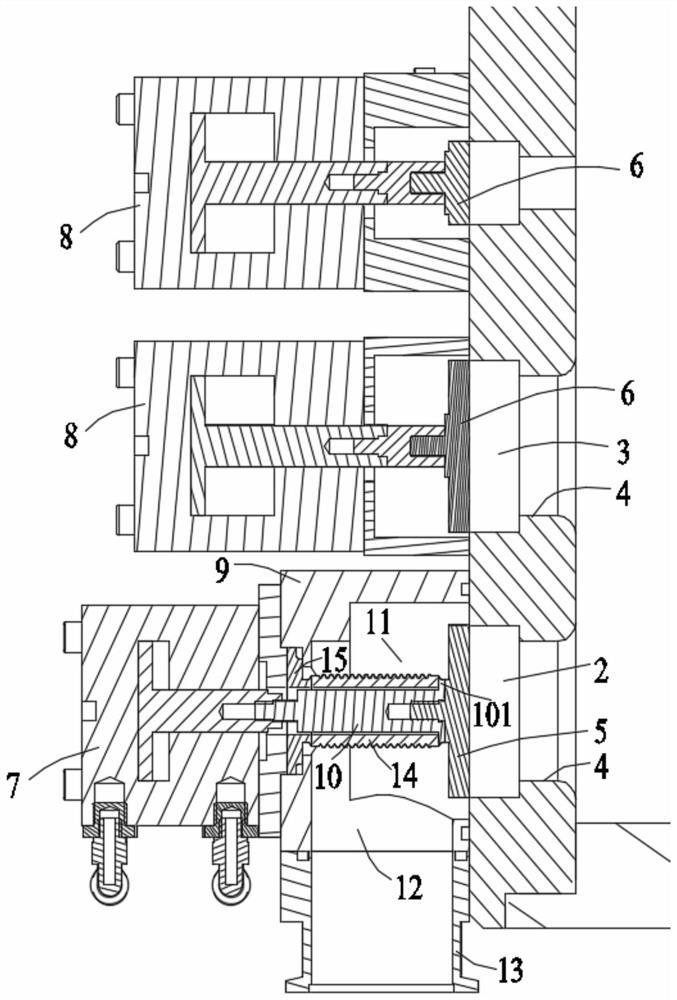
[0034] The outer surface of one side of the vacuum chamber body 1 is provided with an air outlet 2 and two air inlets 3, and the air outlet 2 and the air inlet 3 each have an inner wall near one end of the vacuum chamber body 1. The flange portion 4 protruding radially inward, a first flange 5 is embedded in the air inlet 2, a second flange 6 is embedded in the air inlet 3, and the first flange 5 is embedded in the air inlet 3. 5. The end face of each end of the second flange 6 is in contact with the end face of the corresponding flange portion 4, and the other ends of the first flange 5 and the second flange 6 are in ...

Embodiment 2

[0044] Embodiment 2: A multifunctional vacuum dispensing device, comprising a sealing chamber 1, a frame 16, a dispensing valve 17 and a workbench 18, the sealing chamber 1 is installed on the frame 16, the dispensing valve 17 and The workbenches 18 are all located in the sealing chamber 1, and the dispensing valve 17 is located directly above the workbenches 18;

[0045] The outer surface of one side of the vacuum chamber body 1 is provided with an air outlet 2 and two air inlets 3, and the air outlet 2 and the air inlet 3 each have an inner wall near one end of the vacuum chamber body 1. The flange portion 4 protruding radially inward, a first flange 5 is embedded in the air inlet 2, a second flange 6 is embedded in the air inlet 3, and the first flange 5 is embedded in the air inlet 3. 5. The end face of each end of the second flange 6 is in contact with the end face of the corresponding flange portion 4, and the other ends of the first flange 5 and the second flange 6 are ...


PUM


Abstract

The invention discloses a multifunctional vacuum dispensing device which comprises a sealing bin, a rack, a dispensing valve and a workbench, the sealing bin is installed on the rack, and an extraction opening and two air inlets are formed in the outer surface of one side of a vacuum bin body; the inner wall of the end, close to the interior of the vacuum bin body, of each of the extraction opening and the air inlet is provided with a flange part extending inwards in the radial direction, a first flange plate is embedded into the extraction opening, a second flange plate is embedded into the air inlet, and a weighing mechanism is arranged on the workbench. The weighing mechanism comprises a base installed on the workbench, a movable carrier plate installed on the upper portion of the base and a material cup placed on the upper surface of the movable carrier plate, the two ends of the movable carrier plate correspond to the two end faces of the base in a one-to-one mode, and the movable carrier plate is connected with the two end faces of the base in a matched mode through a guide part and a movable part, so that the movable carrier plate can move up and down relative to the base. According to the invention, the weight of liquid in a vacuum environment is measured, and the problem that electronic weighing equipment in a vacuum bin body is difficult to use is solved.

Description

technical field [0001] The invention relates to the technical field of vacuum cavity sealing, in particular to a multifunctional vacuum dispensing device. Background technique [0002] The vacuum chamber is mainly used in the field of product dispensing and packaging. Using the force of negative pressure, the air in the vacuum box is first pumped away during the pouring process, and then the product is poured, which can quickly penetrate the glue into the product and inject shock. And the bubbles generated by the contact between the glue and the product can also be quickly removed under the action of negative pressure, thus ensuring the high performance of the product. [0003] As the frequency of product updates and iterations continues to accelerate, the importance of the stability and efficiency of mass production equipment in the manufacturing industry is self-evident. In the process of controlling and distributing the fluid in the multi-functional vacuum dispensing dev...

Claims


Application Information

Patent Timeline
Patent Type & Authority Applications(China)
IPC IPC(8): B05C5/02B05C11/00
CPCB05C5/02B05C11/00Y02P70/50
Inventor 陈晓峰杨春雨
Owner SUZHOU TERUITE ROBOT CO LTD
Why Eureka
Try Eureka