Motion camera fixing device and method

A technology for fixing devices and moving cameras, which is applied in the direction of cameras, camera bodies, supporting machines, etc. It can solve problems such as insufficient stability of tripod support, narrow use range of tripods, and inability to guarantee the position of the center of gravity of tripod movement. Achieve the effect of simple and convenient fixed operation

Pending Publication Date: 2022-07-05
深圳市贝克影音数码科技有限公司
View PDF0 Cites 0 Cited by
  • Summary
  • Abstract
  • Description
  • Claims
  • Application Information

AI Technical Summary

Problems solved by technology

[0003] The existing sports camera fixing device mainly has the following technical defects: one, when the sports camera is installed with lenses of different weights, the center of gravity of the combination of the lens and the camera will be changed by the lenses of different weights, and the set and The threaded hole connecting the tripod is in a fixed position, which makes it impossible to ensure that the tripod is at the center of gravity of the movement, which leads to the problem of insufficient stability of the tripod support; secondly, the photographer usually uses the tripod to shoot with the mirror, and the weight of the camera is different , the gravity of the tripod is also different. The fixed force of the traditional tripod for the action camera is a constant value, which leads to the fact that the tripod can only be used for the action camera within the specified weight range, resulting in the problem that the use range of the tripod is narrow.

Method used


Image

  • Motion camera fixing device and method
  • Motion camera fixing device and method
  • Motion camera fixing device and method

Examples


Embodiment

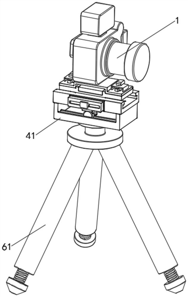
[0042] see Figure 1-Figure 9 , a motion camera fixing device, including a camera 1, a connecting device 2 is fixedly installed on the lower side of the camera 1, a clamping device 3 is arranged on the connecting device 2, and a moving device 4 is fixedly connected to the lower side of the connecting device 2, and the connecting device The front side of 2 is fixedly connected with a control device 5, and the lower side of the motion device 4 is fixedly installed with a detection device 6;

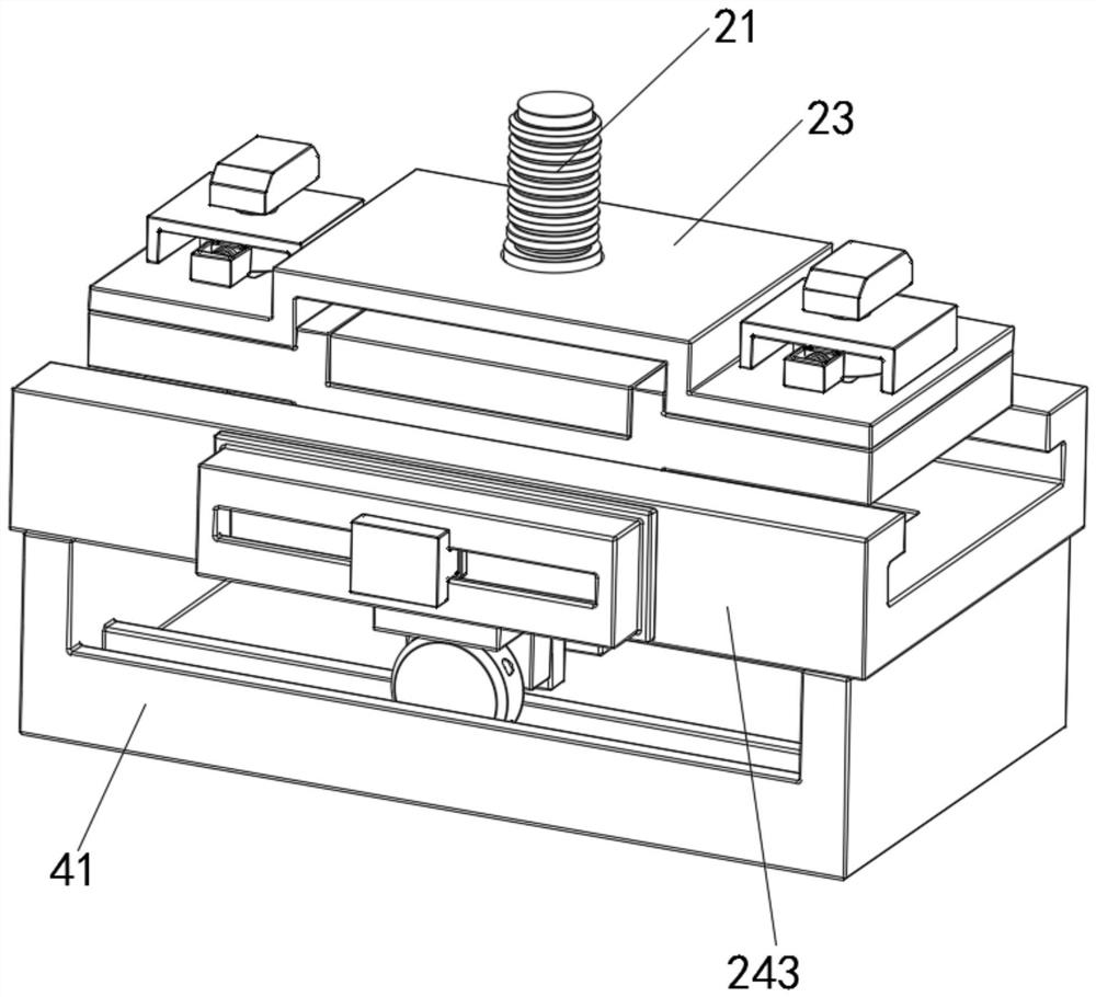
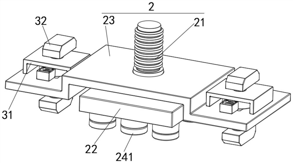
[0043] The connecting device 2 includes a fixing screw 21 , a connecting magnetic block 22 , a fixing plate 23 and a reinforcing device 24 . The lower side of the camera 1 is screwed with a fixing screw 21 , and the lower side of the fixing screw 21 is fixedly connected with a connecting magnetic block 22 , and the fixing screw 21 A fixing plate 23 is fixedly connected to the axial outer side of the magnetic block 22 , and a reinforcing device 24 is provided on the lower side of the connect...


PUM


Abstract

The invention relates to the technical field of motion cameras, and discloses a motion camera fixing device and a fixing method.The motion camera fixing device comprises a camera, a connecting device is fixedly installed on the lower side of the camera, a clamping device is arranged on the connecting device, and a motion device is fixedly connected to the lower side of the connecting device; the connecting device comprises a fixing screw rod, a connecting magnetic block, a fixing plate and a reinforcing device, the lower side of the camera is spirally connected with the fixing screw rod, the lower side of the fixing screw rod is fixedly connected with the connecting magnetic block, the axial outer side of the fixing screw rod is fixedly connected with the fixing plate, and the lower side of the connecting magnetic block is provided with the reinforcing device. According to the invention, through the cooperation of the camera, the shifting block, the slide rheostat, the first coil and the connecting magnetic block, the forward change of the magnetic force of the first coil to the connecting magnetic block and the weight of the camera is realized, so that the purpose of reasonably adapting the fixing force according to the weight of the camera is achieved.

Description

technical field [0001] The invention relates to the technical field of motion cameras, in particular to a motion camera fixing device and a fixing method. Background technique [0002] Action camera refers to a multi-functional camera with a video recorder. Action cameras can be installed in places where traditional cameras and smartphones cannot be installed. The fixation of the camera is mainly carried out through a tripod. With the continuous development of technology, the tripod used for cameras The development trend is also gradually tending to the direction of diversification. [0003] The existing motion camera fixing devices mainly have the following technical defects: First, when the motion camera is installed with lenses of different weights, the center of gravity of the combination of the lens and the camera will be changed by the lenses of different weights. The threaded hole of the tripod is a fixed position, which makes it impossible to ensure that the tripod ...

Claims


Application Information

Patent Timeline
IPC IPC(8): F16M11/04F16M11/18F16M11/22G03B17/56
CPCF16M11/043F16M11/18F16M11/22G03B17/561F16M2200/08
Inventor 胡志辉王善明蔡芳
Owner 深圳市贝克影音数码科技有限公司
Why Eureka
Try Eureka