
Ventilator wind power control test tool platform and use method

A technology for testing tooling and wind control, which is applied in the testing of machines/structural components, measuring devices, wind power generation, etc., and can solve problems affecting the ventilation effect and differences of ventilators

Active Publication Date: 2022-07-05
SICHUAN BLOWER MFR
View PDF13 Cites 2 Cited by
  • Summary
  • Abstract
  • Description
  • Claims
  • Application Information

AI Technical Summary

Problems solved by technology

When testing the ventilation effect of the ventilator, the gas flow velocity sensor is generally installed directly on the ventilating side of the ventilator to measure the air volume velocity. The difference affects the actual ventilation effect of the fan

Method used


Image

  • Ventilator wind power control test tool platform and use method
  • Ventilator wind power control test tool platform and use method
  • Ventilator wind power control test tool platform and use method

Examples


Embodiment 1

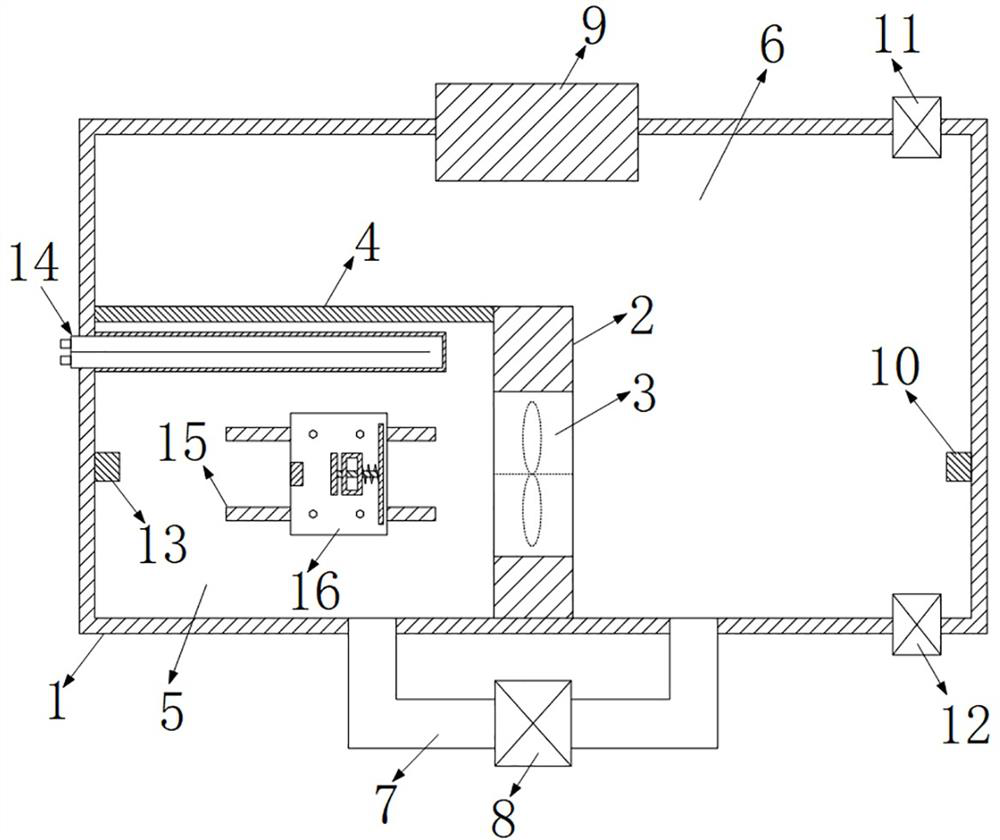
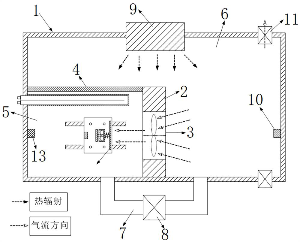
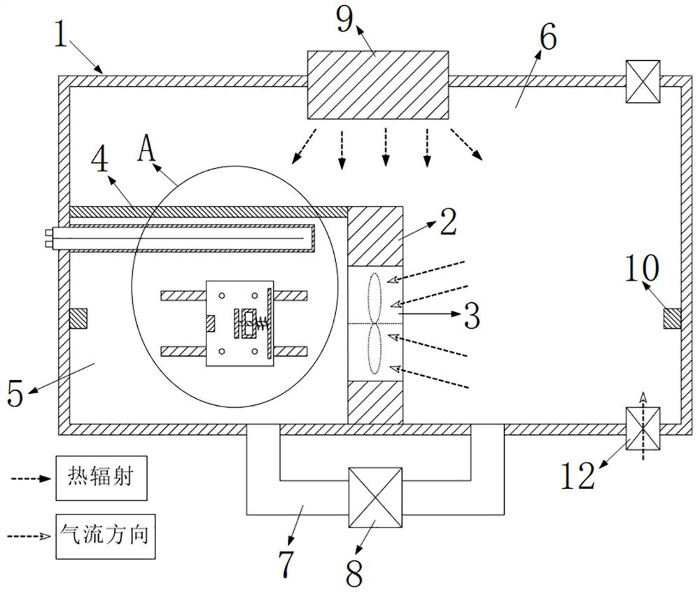
[0024] see Figure 1 to Figure 5 , the main structural features of the ventilator wind control test tooling platform in the present invention are as follows:

[0025] Sealed cabin 1: The fan installation baffle 2 and the heat-absorbing baffle 4 are set inside, thereby forming an inner simulation cavity 5 and an outer simulation cavity 6. The sealing cabin 1 has an integral structure around it, and a removable or flip cover can be set on the upper side. Sealing strips are arranged at the positions where the cover plate and the lower vertical plate (for example, the heat absorption baffle 4 and the fan installation baffle 2 ) are connected.

[0026] Fan installation partition 2: The fan 3 is installed at the position of the fan installation partition 2, and the fan installation partition 2 is provided with an installation position for installing the fan 3.

[0027] Heat-absorbing partition 4: The heat-absorbing partition 4 is made of an alloy material with good thermal conducti...

Embodiment 2

[0044] The present invention relates to a method of using a fan wind control test tooling platform, and the specific contents are as follows:

[0045] The first step is to install the fan 3 to be tested, and the fan 3 is installed at the position of the fan installation partition 2. After the entire sealed cabin 1 is installed, the system starts to activate the heating module 9, and at the same time, the proportional valve 8 of the ventilation connecting pipe 7 is closed. The external temperature sensing module 10 monitors the ambient temperature in the external simulated cavity 6 in real time, and the internal temperature sensing module 13 detects the ambient temperature in the internal simulated cavity 5 in real time.

[0046] In the second step, the heating module 9 heats the heat-absorbing baffle 4, and the thermal radiation energy absorbed by the heat-absorbing baffle 4 is quickly transferred to the inner simulation cavity 5, and at the same time, the temperature-adjustin...

Embodiment 3

[0052] In the present invention, to maintain the correlation mapping relationship between the temperature of the inner simulation cavity 5 and the temperature of the outer simulation cavity 6, the guide rail 15, the base plate 16, the test components, etc. can be placed in the outer simulation cavity 6, and the air outlet side of the fan 3 can be placed in the outer simulation cavity 6. In the external simulation cavity 6, the ventilator 3 blows air toward the external simulation cavity 6, and the air flow blowing effect of the ventilator 3 from the workshop environment to the outside world is tested. Airflow effects are fully tested.


PUM


Abstract

The invention discloses a ventilator wind power control test tool platform and a use method, and relates to the technical field of ventilation test. An inner simulation cavity is formed in one side of a fan mounting partition plate and a heat absorption partition plate, an outer simulation cavity is formed in the other side of the fan mounting partition plate and the heat absorption partition plate, a fan is mounted on the fan mounting partition plate, and a ventilation connecting pipe for communicating the inner simulation cavity with the outer simulation cavity is arranged in a sealed cabin. The sealed cabin is fixedly provided with a heating module, an external temperature sensing module, an exhaust air pressure valve and an air inlet air pressure valve which are located in the outer simulation cavity, the sealed cabin is fixedly provided with an internal temperature sensing module and a temperature adjusting pipe which are located in the inner simulation cavity, and a base plate moving in a directional mode is installed in the inner simulation cavity. The substrate is provided with a test assembly directly facing the ventilator and a distance sensing module used for sensing and detecting the moving distance of the test assembly. According to the invention, the ventilation efficiency of the ventilator in actual use environments of workshops and factories can be conveniently simulated, tested and judged.

Description

technical field [0001] The invention relates to the technical field of ventilation testing, in particular to a fan wind control testing tooling platform and a using method. Background technique [0002] The ventilator is installed in the workshop and workshop area to ventilate the workshop and workshop. After the fan is manufactured, the ventilation test of the fan is carried out to test its ventilation effect in various environments. When testing the ventilation effect of the ventilator, a gas flow rate sensor is generally installed directly on the air outlet side of the ventilator to measure the air flow rate. The difference will affect the actual ventilation effect of the fan. How to test and judge the ventilation intensity and efficiency of the fan in the actual workshop and factory environment has become an item that needs quality inspection after the fan is manufactured and processed. SUMMARY OF THE INVENTION [0003] The technical problem to be solved by the pres...

Claims


Application Information

Patent Timeline
IPC IPC(8): G01M99/00
CPCG01M99/008G01M99/005Y02E10/72
Inventor 朱大银曾雨丰邓海林谷明汉李傲刘洋冉凯王艺雄肖仁刚颜其华
Owner SICHUAN BLOWER MFR
Learn More