Enhanced heat transfer element capable of automatically and transversely scanning fluid

A technology for strengthening heat transfer and first fluid, applied in the field of heat exchange, can solve problems such as reducing the effect of impact heat exchange, and achieve the effects of simple structure, reduced cost, and easy popularization and application.

Pending Publication Date: 2022-07-08
南通中船机械制造有限公司
View PDF0 Cites 0 Cited by
  • Summary
  • Abstract
  • Description
  • Claims
  • Application Information

AI Technical Summary

Problems solved by technology

However, for the conventional steady-state jet impingement heat transfer with a simple hole target structure, when the jet reaches the target surface, a stable flow boundary layer and a thermal boundary layer will be formed near the target surface due to the steady flow of the fluid, and this stable boundary layer layer will reduce the effect of impingement heat transfer

Method used


Image

  • Enhanced heat transfer element capable of automatically and transversely scanning fluid
  • Enhanced heat transfer element capable of automatically and transversely scanning fluid
  • Enhanced heat transfer element capable of automatically and transversely scanning fluid

Examples


Embodiment Construction

[0022] In order to elaborate the technical solutions adopted by the present invention to achieve the predetermined technical purpose, the technical solutions in the embodiments of the present invention will be clearly and completely described below with reference to the accompanying drawings in the embodiments of the present invention. Obviously, the described implementation The examples are only some of the embodiments of the present invention, not all of the embodiments, and the technical means or technical features in the embodiments of the present invention can be replaced without creative work. The following will refer to the accompanying drawings in conjunction with Examples are given to illustrate the present invention in detail.

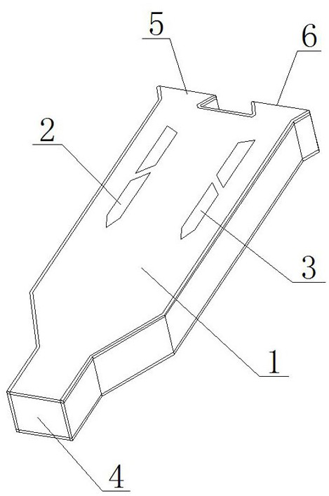
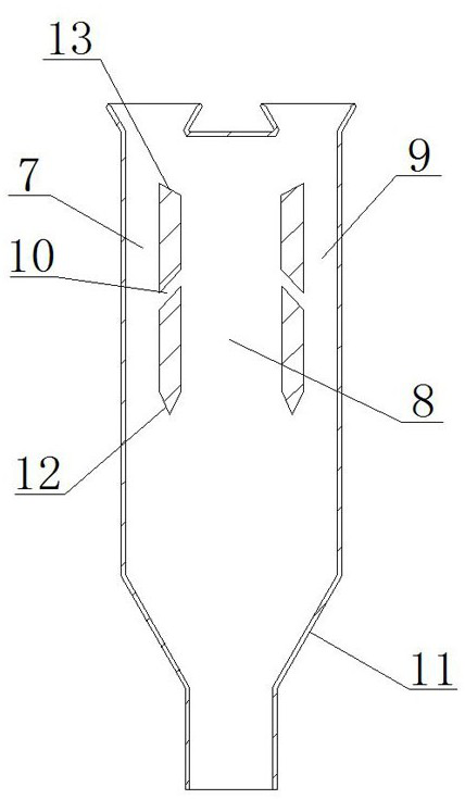
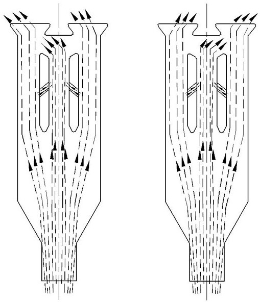
[0023] like figure 1 and figure 2 As shown, an enhanced heat transfer element capable of automatically transversely scanning fluids of the present invention comprises an enhanced heat transfer element housing 1, a first separator 2 and a se...


PUM


Abstract

The invention discloses an enhanced heat transfer element capable of automatically and transversely scanning fluid, which comprises an enhanced heat transfer element shell, a first separator and a second separator, one end of the enhanced heat transfer element shell is provided with a fluid inlet, and the other end of the enhanced heat transfer element shell is provided with a first fluid outlet and a second fluid outlet; the first partition body and the second partition body are fixed in the enhanced heat transfer element shell and divide part of an inner cavity of the enhanced heat transfer element shell into a first side flow channel, a middle flow channel and a second side flow channel in the fluid flowing direction, and disturbance flow channels are further formed in the first partition body and the second partition body. Through the simple structural design, fluid automatically swings, so that a boundary layer on the heat exchange surface is eliminated, and the heat transfer enhancement effect is achieved.

Description

technical field [0001] The invention relates to a heat transfer element, in particular to an enhanced heat transfer element capable of automatically scanning fluid horizontally, and belongs to the technical field of heat exchange. Background technique [0002] In the process of shock heat exchange, when the fluid with the bottom temperature hits the surface of a high-temperature object, it will take away the heat on the surface of the object, thereby cooling the high-temperature components. However, for the traditional steady-state jet impingement heat transfer with a simple hole target structure, when the jet reaches the target surface, a stable flow boundary layer and a thermal boundary layer will be formed near the target surface due to the stable flow of the fluid. layer will reduce the effect of shock heat transfer. [0003] Therefore, it is necessary to design a new heat transfer element to break the flow boundary layer and thermal boundary layer of the stable jet and...

Claims


Application Information

Patent Timeline
Patent Type & Authority Applications(China)
IPC IPC(8): F28F13/02
CPCF28F13/02Y02E10/44
Inventor 顾桂平张磊丁益明
Owner 南通中船机械制造有限公司
Why Eureka
Try Eureka