
Connector of photoelectric combined conduit

An optoelectronic combination and optical fiber connector technology, which is applied in the direction of connection, coupling of optical waveguides, and two-component connection devices, etc., can solve the problems of increasing the risk of using the catheter, increasing the production time and production cost, and the complicated process of installing the catheter, and achieving the realization of The effect of auto-alignment connections

Pending Publication Date: 2022-07-08
SUZHOU MICROPORT ARGUS MEDICAL CORP
View PDF0 Cites 0 Cited by
  • Summary
  • Abstract
  • Description
  • Claims
  • Application Information

AI Technical Summary

Problems solved by technology

[0003] This method has the following disadvantages: 1. The process of producing the catheter needs to temporarily fix the catheter mandrel and the protective sleeve, which increases the production time and production cost
2. The process of installing the conduit is complicated, and the equipment needs to be fully aligned with the conduit to be installed.
3. After the installation is completed, the equipment must keep unfixing the catheter mandrel, which increases the risk of using the catheter

Method used


Image

  • Connector of photoelectric combined conduit
  • Connector of photoelectric combined conduit
  • Connector of photoelectric combined conduit

Examples


Embodiment Construction

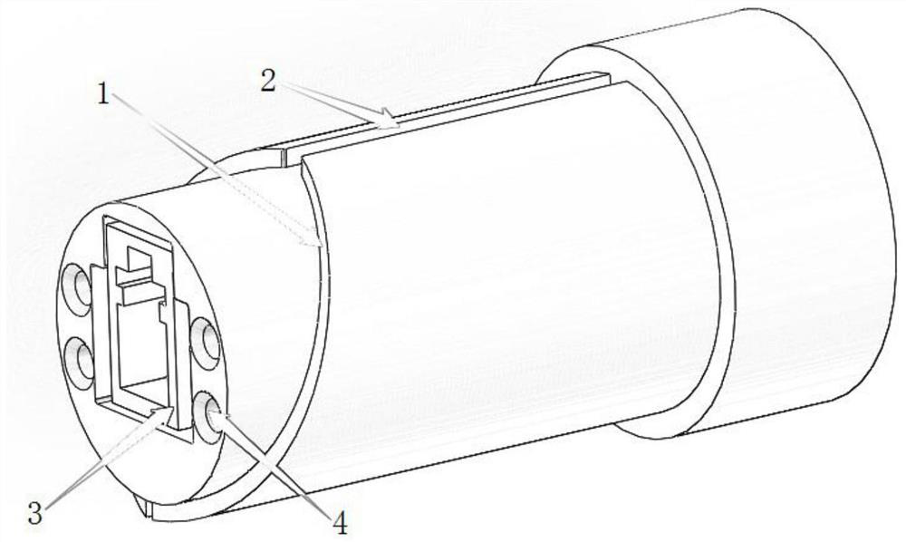
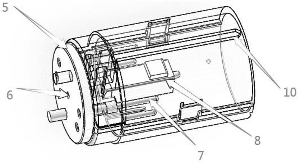
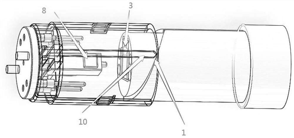
[0029] Exemplary embodiments of the present application are described below, including various details of the embodiments of the present application to facilitate understanding and should be considered as exemplary only. Accordingly, those of ordinary skill in the art will recognize that various changes and modifications of the embodiments described herein can be made without departing from the scope and spirit of the present application. Also, descriptions of well-known functions and constructions are omitted from the following description for clarity and conciseness. In this application, the upper and lower positions are determined according to the incident direction of the light, and the light incident is up.

[0030] The application provides a connector for an optoelectronic composite conduit, comprising a collet part and an outer part, wherein the part of the outer part is located in the collet part,

[0031] The outer part has a guide slide 1 and a positioning groove 2,...


PUM


Abstract

The invention discloses a connector of a photoelectric combined conduit, which comprises a chuck part and an outer wrapping part, the outer wrapping part is partially positioned in the chuck part, the outer wrapping part is provided with a guide slide way and a positioning groove, and one end of the guide slide way is connected with the positioning groove; the chuck part comprises a barrel-shaped main body part, and a guide column is arranged on the inner wall of the main body part. According to the connector of the photoelectric combined conduit, when the outer wrapping component and the chuck component are installed, the chuck component and the outer wrapping component are horizontally placed, and the guide columns enter the positioning grooves along the guide slideways and continue to slide in the positioning grooves; therefore, the wrapping part partially enters the chuck part, and the automatic alignment connection of the optical fiber and the electrode is realized.

Description

technical field [0001] The present application relates to the technical field of medical devices, in particular to a connector for an optoelectronic combined catheter. Background technique [0002] In the process of connecting the combined catheter, the circumferential position of the catheter mandrel is not fixed because the catheter needs to be rotated. However, the catheter needs to be positioned and aligned in the circumferential direction during the installation of the catheter, so that the optical and electrical components can be inserted into the device at the same time. In the corresponding position of the device, the main alignment method on the market is to fix the position of the catheter mandrel and the outer protective tube of the catheter when the catheter is produced. During the installation process, the equipment must first be aligned with the catheter. position, and then slowly push the connection by the device motor. Then, the structure for fixing the cath...

Claims


Application Information

Patent Timeline
Patent Type & Authority Applications(China)
IPC IPC(8): H01R24/00H01R13/631H01R13/502H01R13/02G02B6/38
CPCH01R24/005H01R13/631H01R13/02H01R13/502G02B6/3817G02B6/3838A61M25/0082A61M25/0043A61M39/10H01R2201/12
Inventor 李涛明良裕吴振英张林涛
Owner SUZHOU MICROPORT ARGUS MEDICAL CORP
Learn More