Outdoor prefabricated substation

A prefabricated substation, outdoor technology, applied in the field of substations, can solve the problems of easy occurrence of waterlogging, easy to be affected by outdoor environment, affecting the safety of electrical appliances in prefabricated cabins, etc., to achieve the effect of improving the protection effect

Pending Publication Date: 2022-07-08
姚凌云
View PDF1 Cites 0 Cited by
  • Summary
  • Abstract
  • Description
  • Claims
  • Application Information

AI Technical Summary

Problems solved by technology

[0004] In the existing technology, since the prefabricated substation is directly located outdoors, it is easily affected by the outdoor environment, especially in rainy weather, and under the condition of short-term heavy rain, waterlogging is prone to occur. The prefabricated substation is directly placed in stagnant water. It is easy to penetrate into the interior of the prefabricated cabin, thereby affecting the safety of electrical appliances inside the prefabricated cabin

Method used


Image

  • Outdoor prefabricated substation
  • Outdoor prefabricated substation
  • Outdoor prefabricated substation

Examples


Embodiment 1

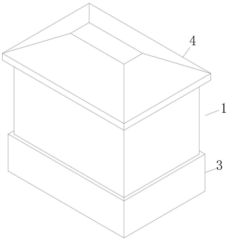
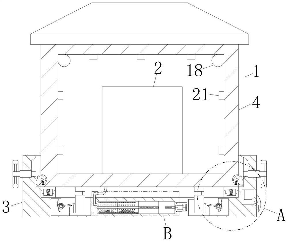
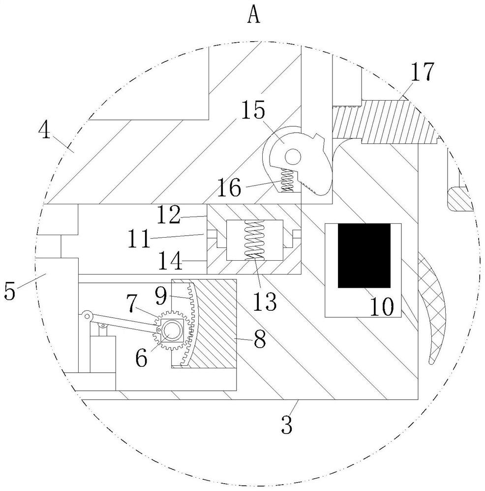
[0029] like Figure 1-Figure 3As shown, an outdoor prefabricated substation according to an embodiment of the present invention includes a prefabricated cabin 1 and a built-in transformer equipment 2; the interior of the prefabricated cabin 1 is provided with a built-in transformer equipment 2; the prefabricated cabin The body 1 includes a base 3 and an upper cabin 4; the top surface of the base 3 is provided with a chute; the interior of the chute is slidably connected with the upper cabin 4; the interior of the base 3 is provided with a jack 5; The surface of the lifting handle of the jack 5 is fixedly connected with the first motor 6; the surface of the lifting handle of the jack 5 is rotatably connected with a gear 7, and the gear 7 and the output shaft of the first motor 6 are fixedly connected; A guide block 8 is fixedly connected inside; a side surface of the guide block 8 relative to the gear 7 is provided with a mounting groove; the interior of the mounting groove is ...

Embodiment 2

[0038] like Figure 5 As shown in the comparison example 1, another embodiment of the present invention is: the inside of the swivel ring 27 is provided with evenly arranged guide holes 29; the inner surface of the swivel ring 27 is provided with evenly arranged through holes 30; During operation, by opening the guide hole 29 and the through hole 30 inside the swivel ring 27, and through the movement of the pressure control block 24, the squeezing gas is directly introduced into the inside of the guide hole 29, and then the gas will enter the through hole through the guide hole 29. Inside the hole 30 , gas is injected into the inside of the swivel ring 27 through the through hole 30 , so as to improve the mixing effect of the dry powder 20 inside the swivel ring 27 .

[0039] The position of the connecting hole 28 is close to the bottom position of the partition plate 25; during operation, by opening the connecting hole 28 at the bottom position close to the partition plate 25...


PUM


Abstract

The invention belongs to the field of transformer substations, and particularly relates to an outdoor prefabricated transformer substation which comprises a prefabricated cabin and built-in transformation equipment. Built-in transformation equipment is arranged in the prefabricated cabin body; the prefabricated cabin body comprises a base and an upper cabin body; a sliding groove is formed in the top face of the base. An upper cabin body is slidably connected to the interior of the sliding groove; a jack is arranged in the base; a fixing cavity is formed in the base; a water sensor is fixedly connected to the interior of the fixed cavity; the split design of the prefabricated cabin body is effectively achieved, the upper cabin body of the prefabricated cabin body can move up and down, the height of the upper cabin body can be automatically adjusted up and down according to the environmental condition, and when water is accumulated around the prefabricated cabin body, the problem that a large amount of accumulated water permeates into the prefabricated cabin body is solved; and the protection effect on the built-in transformation equipment is improved.

Description

technical field [0001] The invention belongs to the field of substations, in particular to an outdoor prefabricated substation. Background technique [0002] Prefabricated substations can be used as ring-type and terminal-type transformation and distribution devices, and are widely used in residential quarters, industrial and mining enterprises, hotels, hospitals, shopping malls, airports, parks, railways and other outdoor places. For maintenance, etc., as close as possible to the load center, reduce the length of the incoming and outgoing cables, take measures to prevent flooding according to the installation environmental conditions, and do a good job in the installation of the grounding device. [0003] Publication No. CN108521095A is an outdoor prefabricated substation. Through the dust collection water tank and the air outlet, the air inside the substation is discharged into the substation after passing through the water, which can effectively improve the humidity of th...

Claims


Application Information

Patent Timeline
IPC IPC(8): H02B7/06H02B1/50H02B1/28A62C31/03A62C37/42
CPCH02B7/06H02B1/505H02B1/28A62C31/03A62C37/42
Inventor 姚凌云
Owner 姚凌云
Why Eureka
Try Eureka