Building template surface spraying device

A technology of surface spraying and building formwork, applied in the direction of spraying device, etc., can solve problems such as inconvenience of use, and achieve the effect of reducing spraying waste, reducing covering spraying, and preventing leaving gaps

Pending Publication Date: 2022-07-15
王大超
View PDF0 Cites 1 Cited by
  • Summary
  • Abstract
  • Description
  • Claims
  • Application Information

AI Technical Summary

Problems solved by technology

[0005] In order to overcome the above-mentioned patent, when spraying the template, it is necessary to manually pick up the template, so that the nozzle can spray the template, which is inconvenient to use. The technical problem of the present invention is: to provide a It is easy to place and spray the formwork, and it is a convenient spraying device for the surface of building formwork

Method used


Image

  • Building template surface spraying device
  • Building template surface spraying device
  • Building template surface spraying device

Examples


Embodiment 1

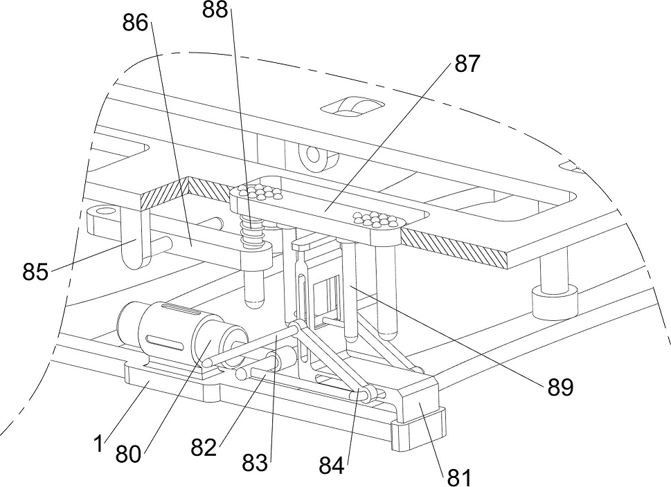
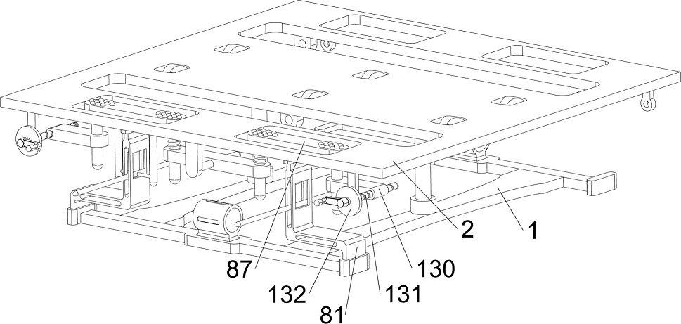
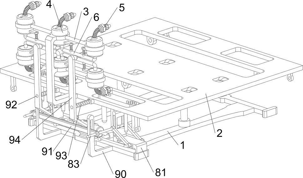
[0081] A construction formwork surface spraying device, such as Figure 1-Figure 7 As shown, it includes a base 1, a support plate 2, a support frame 3, a spraying tank 4, a stretching nozzle 5, a moving push rod 6, a first return spring 7, a jacking mechanism 8 and a spraying mechanism 9. The top of the base 1 is provided with There is a support plate 2, which is used to place the formwork. The support plate 2 is provided with a support frame 3 on the front and rear sides. The upper and lower sides of the two support frames 3 are evenly spaced with three spraying cans 4. There are twelve spraying cans 4, which are used for To store the paint, the twelve spraying cans 4 are provided with sliding plugs for injecting an appropriate amount of paint into the spraying cans 4, and the tops of the six spraying cans 4 above are all slidingly provided with stretching nozzles 5, The six spraying cans 4 below are also slidably provided with six stretching nozzles 5. The stretching nozzle...

Embodiment 2

[0086] On the basis of Example 1, as figure 1 , figure 2 , Figure 8 and Figure 9As shown, it also includes a moving mechanism 10. The moving mechanism 10 includes a first support rod 100, a first electric sliding rail 101, a second electric sliding rail 102, a first electric sliding block 103, a third connecting rod 104 and a second electric sliding rail 102. The electric slider 105, the front and rear sides of the support plate 2 are symmetrically provided with first support rods 100, the tops of the four first support rods 100 are all installed with first electric slide rails 101, and the tops of the four first electric slide rails 101 are A second electric slide rail 102 is provided, the lower part of the inner side of the four first electric slide rails 101 is slidably provided with a first electric slider 103, and the upper part of the inner side of the four second electric slide rails 102 is slidably provided with a second electric slide rail 103. Electric sliders ...


PUM


Abstract

The invention relates to a spraying device, in particular to a building template surface spraying device. According to the building formwork surface spraying device, a formwork can be placed, spraying can be conveniently conducted on the formwork, and using is convenient. A building formwork surface spraying device comprises a supporting plate, a spraying device body and a spraying device body, the supporting frames are arranged on the front side and the rear side of the supporting plate; the three spraying tanks are uniformly arranged on the upper side and the lower side of the two supporting frames at intervals, and the number of the spraying tanks is twelve; and the stretching spray pipes are arranged at the tops of the six spraying tanks on the upper portion in a sliding mode. A push rod drives a first connecting rod to move towards the inner side, the first connecting rod drives an ejector rod to move towards the upper side in the process of moving towards the inner side, the ejector rod drives a second connecting rod to move towards the upper side, the second connecting rod drives a friction plate to move towards the upper side, and the friction plate pushes a template to move towards the upper side, so that the template can be assisted to move towards the upper side; and paint can be conveniently smeared on the side face of the formwork.

Description

technical field [0001] The invention relates to a spraying device, in particular to a surface spraying device for a building template. Background technique [0002] Building formwork is a kind of building material widely used in construction projects. Aluminum alloy building formwork is widely used because of its light weight, high strength, flexible disassembly and assembly, long service life and high recycling value. The surface is sprayed to facilitate subsequent demoulding and recycling of building formwork. [0003] Patent application CN212791572U, published on 20210326, discloses a construction template surface spraying device, including a paint bucket, a high-pressure paint pump with inlet and outlet pipes, and a spray head, the high-pressure paint pump is provided with a connecting line, and the connecting line A switch and a power plug are installed, and it is characterized in that: it also includes a base and a rotating mechanism; the base is provided with a parti...

Claims


Application Information

Patent Timeline
Patent Type & Authority Applications(China)
IPC IPC(8): B05B13/04B05B13/02B05B14/00B05B15/68B05B12/12
CPCB05B13/041B05B13/0221B05B12/12B05B15/68B05B14/00
Inventor 王大超
Owner 王大超
Why Eureka
Try Eureka