
Wheel braking device for riding bicycle

A brake device, wheel technology, applied in the direction of bicycle brakes, bicycle accessories, etc.

Inactive Publication Date: 2022-07-22
赵林
View PDF0 Cites 0 Cited by
  • Summary
  • Abstract
  • Description
  • Claims
  • Application Information

AI Technical Summary

Problems solved by technology

[0006] The purpose of the present invention is to solve the problem that brake pads and bearings belong to different fields, and it is difficult to combine these two fields to achieve braking effect in the prior art. bicycle wheel brakes

Method used


Image

  • Wheel braking device for riding bicycle
  • Wheel braking device for riding bicycle
  • Wheel braking device for riding bicycle

Examples


Embodiment Construction

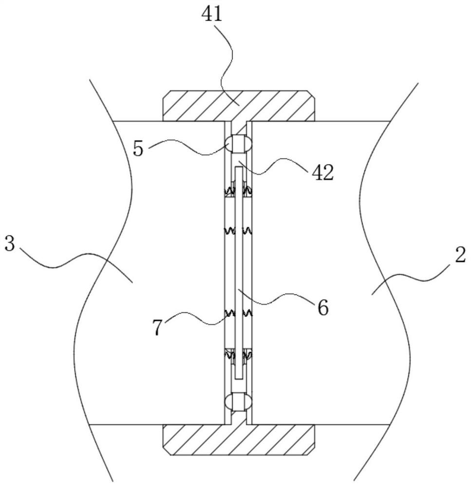
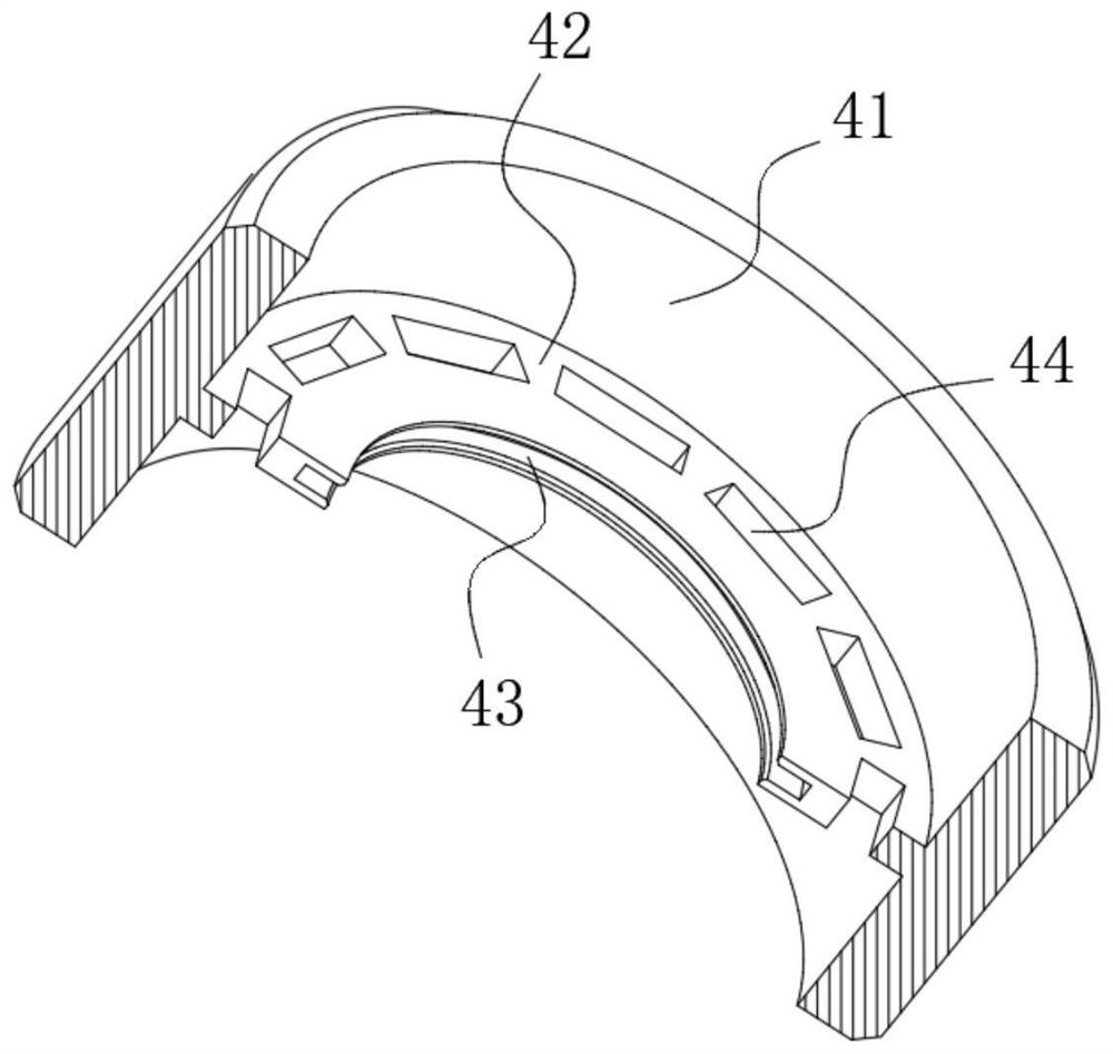
[0028] refer to Figure 1-9 , a wheel braking device for riding a bicycle, comprising a fixed shaft 1 and a first sleeve 2 and a second sleeve 3 respectively sleeved on both ends of the steel ball accommodating frame 4, the first sleeve 2, the second sleeve Both the tube 3 and the steel ball accommodating frame 4 are sleeved on the fixed shaft 1. It should be noted that the first sleeve 2 and the second sleeve 3 are coaxially arranged with the same bicycle wheel, and the first sleeve 2 and the second sleeve are The second sleeve 3 slides coaxially with the bicycle wheel but does not rotate, so as to ensure that the first sleeve 2 and the second sleeve 3 can also be rotated on the fixed shaft 1 together with the first sleeve 2 and the second sleeve 3 when the bicycle wheel starts to rotate, but The sliding and rotation of the first sleeve 2 and the second sleeve 3 on the fixed shaft 1 will not be affected.

[0029] Wherein, both the first sleeve 2 and the second sleeve 3 rotat...


PUM


Abstract

The wheel braking device comprises a fixing shaft, a first sleeve and a second sleeve, the two ends of a steel ball containing frame are sleeved with the first sleeve and the second sleeve respectively, the fixing shaft is sleeved with the first sleeve, the second sleeve and the steel ball containing frame, and the first sleeve and the second sleeve rotate synchronously with the steel ball containing frame. The steel ball containing frame comprises a lantern ring, a containing ring plate, a supporting ring containing groove and a plurality of mounting cavities. The end fixing plates are arranged on the opposite side walls of the mounting cavity, it can be guaranteed that the first sleeve or the second sleeve extrudes the first steel ball movable frame and the second steel ball movable frame between the sliding rods and is not hindered by the end fixing plates, and the first steel ball movable frame and the second steel ball movable frame stretch out and draw back in the mounting cavity; it needs to be explained that the diameter of the braking steel ball is larger than the thickness of the mounting cavity, and therefore it can be guaranteed that the first sleeve or the second sleeve extrudes the braking steel ball and is not hindered by the placing annular plate.

Description

technical field [0001] The present invention relates to the technical field of wheel braking, and in particular, to a wheel braking device for riding a bicycle. Background technique [0002] At present, the way to brake the wheel of the bicycle is to use the brake pad to brake effectively. This kind of brake often has the following problems: [0003] First of all, in the existing braking system, the pressure between the brake pad and the wheel is increased to increase the friction so that the wheel can stop in time. At the same time, this braking method requires frequent replacement of the brake pad. To ensure the normal operation of braking, the way of frequently replacing the brake pads is not conducive to the improvement of braking efficiency; [0004] Secondly, the rolling of the wheel is rolled on the shaft, and this method requires the participation of the rolling bearing. Braking the steel ball in the rolling bearing can also have a certain braking effect, but the br...

Claims


Application Information

Patent Timeline
Patent Type & Authority Applications(China)
IPC IPC(8): B62L1/00B62L1/02
CPCB62L1/005B62L1/02
Inventor 赵林
Owner 赵林
Learn More