Dynamic balance correcting device
A technology of calibration device and mounting seat, which is applied in static/dynamic balance testing, measurement device, and optical device, etc., can solve the problem of small detection range and so on.
- Summary
- Abstract
- Description
- Claims
- Application Information
AI Technical Summary
Problems solved by technology
Method used
Image

Examples
no. 1 example
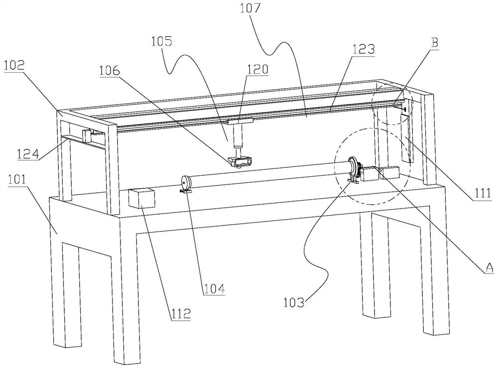
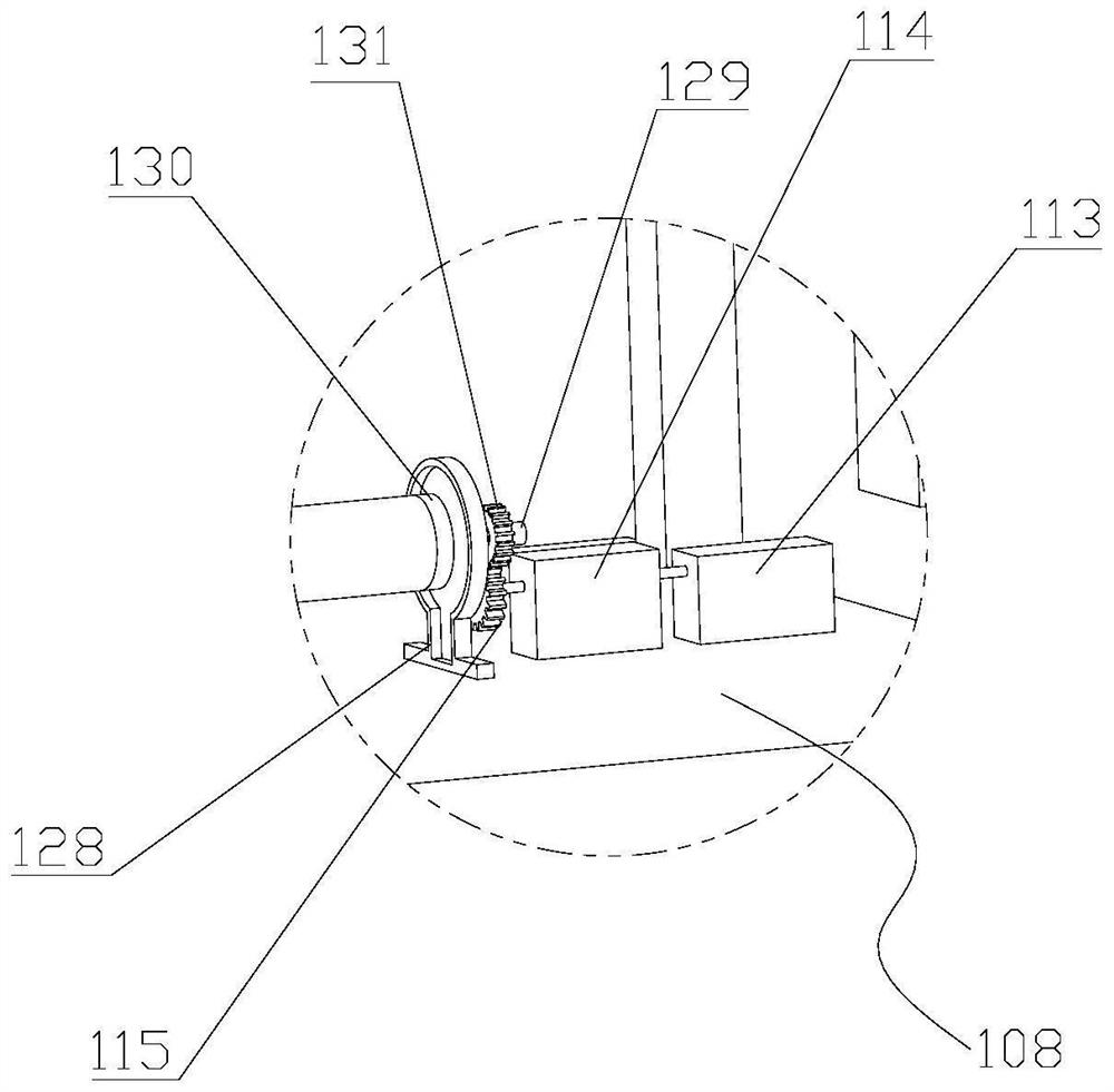
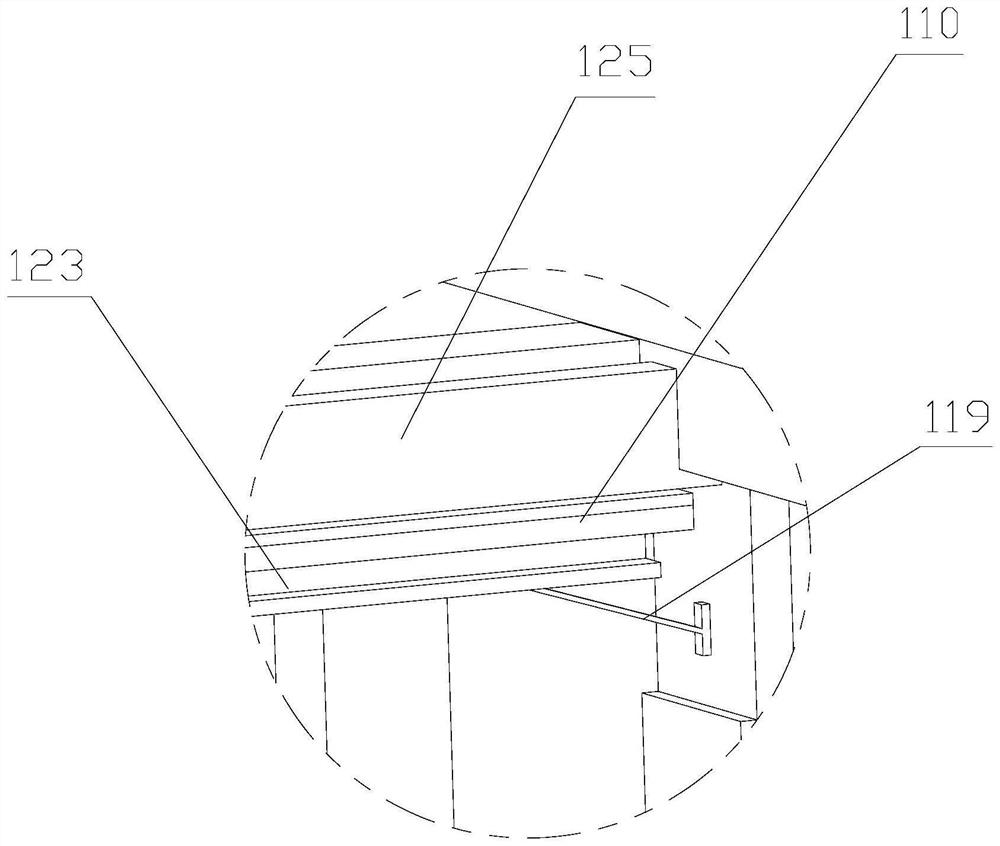
[0027] see Figure 1 to Figure 4 ,in figure 1 is the structure diagram of the dynamic balance correction device, figure 2 Yes figure 1 The enlarged view of the local structure at A, image 3 Yes figure 1 The enlarged view of the local structure at B, Figure 4 It is a schematic diagram of the connection structure of the push assembly and the mounting seat. The present invention provides a dynamic balance correction device, comprising a detection table 101, a bracket 102, a first bracket 103, a second bracket 104, a mounting seat 105, a laser detector 106, a position detection mechanism 107 and a rotation mechanism 108. The position detection mechanism 107 includes a push assembly 109 , a first scale bar 110 , a second scale bar 111 and a control panel 112 , and the rotation mechanism 108 includes a drive motor 113 , a gear reduction box 114 and an output gear 115 , the push assembly 109 Including a first servo motor 116 , a first screw 117 , a first screw sleeve 118 and...
no. 2 example
[0035] On the basis of the first embodiment, see Figure 5 and Image 6 , Figure 5 is a schematic structural diagram of the dynamic balance correction device of the second embodiment, Image 6 for Figure 5 A magnified view of the local structure at C. The present invention provides a dynamic balance correction device further comprising an auxiliary support frame 201 , and the auxiliary support frame 201 includes a bottom plate 202 , a support plate 203 and an arc-shaped plate 204 .
[0036] For this specific embodiment, the auxiliary support frame 201 is located between the first bracket 103 and the second bracket 104 , and the auxiliary support frame 201 is used to support the carbon fiber roller. The auxiliary support frame 201 is arranged between the 103 and the second bracket 104, and the auxiliary support frame 201 is used to support the carbon fiber roller, so that the structure of the carbon fiber roller is more stable.
[0037] One end of the support plate 203 i...
no. 3 example
[0040] On the basis of the first embodiment, see Figure 7 and Figure 8 , Figure 7 is a schematic structural diagram of the dynamic balance correction device of the third embodiment, Figure 8 for Figure 7 A magnified view of the local structure at D. The present invention provides a dynamic balance correction device further comprising an adjustment mechanism 301, the adjustment mechanism 301 includes a sliding seat 302 and a displacement assembly 303, the displacement assembly 303 includes a second servo motor 304, a second lead screw 305 and a second lead wire Rod sleeve 306.
[0041] According to this specific embodiment, the bottom of the second bracket 104 is provided with the sliding seat 302 , the detection table 101 is further provided with a second sliding rail 307 , and the sliding seat 302 is connected to the second sliding rail. 307 is slidably connected, the detection table 101 is also provided with the displacement component 303, the output end of the dis...
PUM
 Abstract
Description
Claims
Application Information
 - R&D Engineer
- R&D Manager
- IP Professional
- Industry Leading Data Capabilities
- Powerful AI technology
- Patent DNA Extraction
Browse by: Latest US Patents, China's latest patents, Technical Efficacy Thesaurus, Application Domain, Technology Topic.
© 2024 PatSnap. All rights reserved.Legal|Privacy policy|Modern Slavery Act Transparency Statement|Sitemap