Awning frame with deployment holding mechanism

A technology for holding mechanism and awning, which is applied to tents/canopies, building types, buildings, etc., can solve the problems of inconvenient opening or folding, complex structure of awning frame, and high manufacturing cost, and achieves convenient and labor-saving opening and folding. Improved deployment stability and reliability, and lower production costs

Pending Publication Date: 2022-07-29
XIAMEN ROADZUP OUTDOOR PROD
View PDF4 Cites 0 Cited by
  • Summary
  • Abstract
  • Description
  • Claims
  • Application Information

AI Technical Summary

Problems solved by technology

Therefore, it has the following disadvantages: first, when folding, it is necessary to loosen the locking mechanism of each column, the steps are cumbersome, and it is inconvenient to open or fold; second, when opening, it is necessary to push up the sliding seat relative to each column, In order to ensure that multiple columns push up the sliding seat synchronously, multiple people may be required to operate together, and it is necessary to confirm whether each locking mechanism is in the locked state, the steps are cumbersome, and it is inconvenient to open or fold
[0007] The above-mentioned awning frame has a complex structure, many rods, and high manufacturing cost

Method used


Image

  • Awning frame with deployment holding mechanism
  • Awning frame with deployment holding mechanism
  • Awning frame with deployment holding mechanism

Examples


Embodiment 1

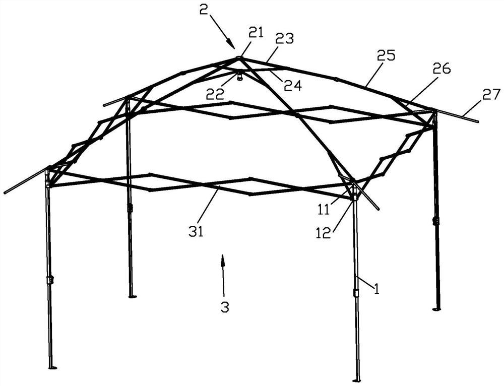
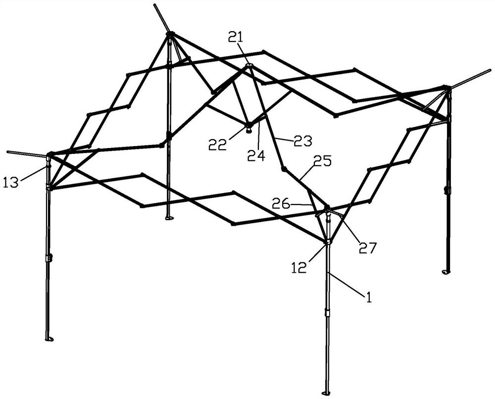
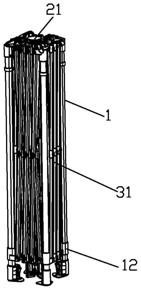
[0047] Please check Figure 1 to Figure 13 , an awning frame with an unfolding and holding mechanism, including N uprights 1, a canopy mechanism 2 and an unfolding and holding mechanism 4, where N is a natural number greater than or equal to 3. A fixing seat 11 is fixed on the top of the column 1, a sliding seat 12 is slidably connected to the column 1, and a limiting mechanism for limiting the sliding seat 12 to the highest position is provided on the column 1. The limiting mechanism can be the one shown in the figure. The limit ring 13 fixed on the column 1 can also be a locking mechanism that directly locks the sliding seat 12 at a predetermined height. The locking mechanism can be a snap lock or a bolt lock, etc.; The arrangement is in a ring-shaped structure, such as a rectangle, a hexagon, etc., and a scissors-type mechanism 3 is connected between the fixed seat 11 and the sliding seat 12 of each adjacent ring-shaped two upright columns 1, and the scissors-type mechanism...

Embodiment 2

[0053] Please check Figure 14 , it differs from the first embodiment in that the unfolding and holding mechanism also includes a second limiting mechanism, the second limiting mechanism replaces the first limiting mechanism, and the second limiting mechanism is connected to the upper connecting seat 21 and the lower connecting The seat 22 also limits the minimum distance between the upper connecting seat 21 and the lower connecting seat 22. It includes a mandrel 211 fixed on the bottom surface of the upper connecting seat 21. The mandrel 211 abuts on the top surface of the lower connecting seat to achieve position limit. The rod is at a deployed angle. According to needs, the first limiting mechanism and the second limiting mechanism may be included at the same time.


PUM


Abstract

The invention discloses an awning frame with an unfolding keeping mechanism. The awning frame comprises stand columns, a ceiling mechanism and the unfolding keeping mechanism. Fixed seats are fixedly arranged at the top ends of the uprights; the ceiling mechanism comprises an upper connecting seat, a lower connecting seat and a plurality of awning rod groups, the upper connecting seat and the lower connecting seat are arranged up and down, the two ends of each awning rod group are respectively connected to the upper connecting seat and the fixed seat in a rotating mode, each awning rod group comprises a first awning rod and a push rod, the first end of each push rod is connected to the corresponding first awning rod in a rotating mode, and each push rod is further connected to the corresponding lower connecting seat in a rotating mode; the unfolding keeping mechanism comprises an elastic body arranged on the lower connecting base, the second end of the push rod extends out of the rotating axis of the push rod and the lower connecting base, the elastic body upwards abuts against the second ends of the push rods of the awning rod sets so that the push rods can be kept at the unfolding angle, and the awning frame can be kept in the unfolding state by keeping the push rods of the awning rod sets at the unfolding angle. The folding chair has the advantages of being convenient and labor-saving to unfold and fold, simple and stable to unfold, low in production cost and convenient and simple to use.

Description

technical field [0001] The present invention relates to camping articles, and more particularly to a pergola stand with an unfolding and retaining mechanism. Background technique [0002] The existing awning frame includes a top connecting seat and a plurality of frame rod groups. The frame pole group includes a column, a canopy pole group and a strut. A fixing seat is fixed on the top of the upright column, and a sliding seat is arranged on the upright column. The canopy rod group includes a first canopy rod and a second canopy rod, the inner end of the first canopy rod is rotatably connected to the top-connecting seat, and the inner end of the second canopy rod is rotatably connected to the outer end of the first canopy rod, so the The outer end of the second canopy rod is rotatably connected to the fixing seat. The lower end of the strut is rotatably connected to the sliding seat, and the upper end is rotatably connected to the second canopy pole. A scissor-type mecha...

Claims


Application Information

Patent Timeline
Patent Type & Authority Applications(China)
IPC IPC(8): E04H15/44E04H15/58E04H15/32
CPCE04H15/44E04H15/58E04H15/32
Inventor 黄长久
Owner XIAMEN ROADZUP OUTDOOR PROD
Why Eureka
Try Eureka